Kenwood KAC-X520 Instruction Manual - Page 8
CENTER UNIT, Wiring, EXT.AMP.CONT. external amplifier control terminal
 |
View all Kenwood KAC-X520 manuals
Add to My Manuals
Save this manual to your list of manuals |
Page 8 highlights
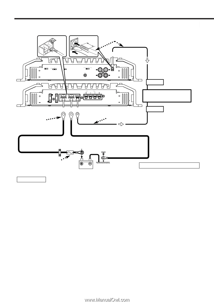
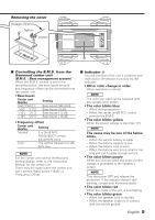
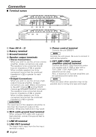
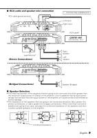
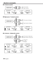
Connection ■ Power wire connection The connecting wire diameter* • If solid wire: Ø0.4 (AWG 26) - Ø1.2 (AWG 16) 11 mm • If multi strand wire: Ø0.4 (AWG 26) - Ø1.2 (AWG 16) INFRASONIC OFF ON B.M.S. OFF REMOTE +12dB FILTER OFF HPF LPF ( OPERATION STEREO MONO(L ch) GND LINE IN LINE OUT EXT.AMP.CONT. L L R R FUSE(30Ax2) POWER IN BATT. GND SPEAKER P.CON OUTPUT BRIDGED LEFT RIGHT 30 30 Lead terminal* Battery wire* @ #$ Extension wire* Ground wire* External amplifier control wire (Pink / Black) (Refer to page 6) EXT.CONT. CENTER UNIT (CD receiver, etc.) P.CONT. Power control wire (Blue/ White) Protective Fuse* Battery * : Commercially available parts 2WARNING To prevent fire caused by a short in the wiring, connect a fusible link or breaker nearby the battery's positive terminal. Wiring •Take the battery wire for this unit directly from the battery. If it's connected to the vehicle's wiring harness, it can cause blown fuses etc. • If a buzzing noise is heard from the speakers when the engine is running, connect a line noise filter (optional) to each of the battery wire. • Do not allow the wire to directly contact the edge of the iron plate by using Grommets. • Connect the ground wire to a metal part of the car chassis that acts as an electrical ground passing electricity to the battery's negative - terminal. Do not turn the power on if the ground wire is not connected. • Be sure to install a protective fuse in the power cord near the battery. The protective fuse should be the same capacity as the unit's fuse capacity or somewhat larger. • For the power cord and ground, use a vehicle type (fireproof) power wring cord with a current capacity greater than the unit's fuse capacity. (Use a power wiring cord with a diameter of 8 mm2 (AWG 8) or greater.) • When more than one power amplifier are going to be used, use a power supply wiring wire and protective fuse of greater current-handling capacity than the total maximum current drawn by each amplifier. EXT.AMP.CONT. (external amplifier control) terminal ( 1. Peel the cladding of wire for a length of 11mm from the end. 2. While pressing the lock release button with a slotted screwdriver, insert the wire. 8 English
-
 1
1 -
2
-
 3
3 -
 4
4 -
 5
5 -
 6
6 -
 7
7 -
 8
8 -
 9
9 -
 10
10 -
 11
11 -
 12
12 -
 13
13 -
14
-
15
-
16
-
17
-
18
-
19
-
20
-
21
-
22
-
23
-
24
-
25
-
26
-
27
-
28
-
29
-
30
-
31
-
32
-
33
-
34
-
35
-
36
-
37
-
38
 |
 |