Kenwood KDCMP332 Instruction Manual - Page 31
Screwing the Faceplate on the Unit
 |
View all Kenwood KDCMP332 manuals
Add to My Manuals
Save this manual to your list of manuals |
Page 31 highlights
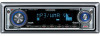
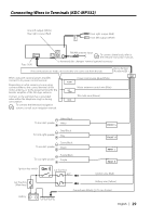
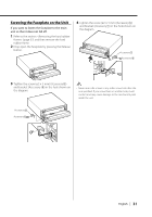
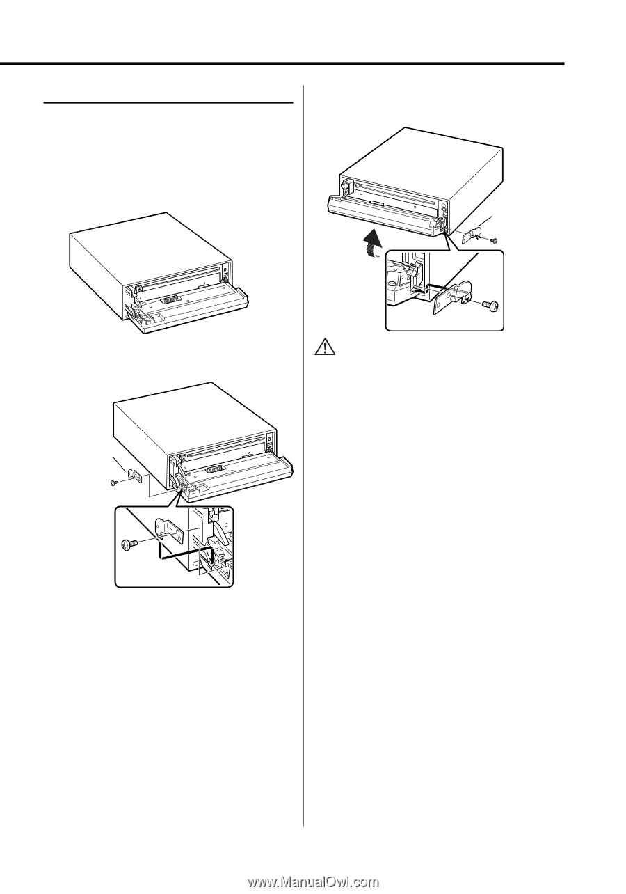
Screwing the Faceplate on the Unit If you want to fasten the faceplate to the main unit so that it does not fall off. 1 Refer to the section (page 32) and then remove the hard rubber frame. 2 Drop open the faceplate by pressing the Release button. 4 Tighten the screw (ø2 × 5 mm) (Accessory5) and bracket (Accessory7) in the hole shown on the diagram. Accessory7 Accessory5 3 Tighten the screw (ø2 × 5 mm) (Accessory5) and bracket (Accessory 6) in the hole shown on the diagram. • Never insert the screws in any other screw hole than the one specified. If you screw them in another hole, it will contact and may cause damage to the mechanical parts inside the unit. Accessory6 Accessory5 English | 31
-
 1
1 -
2
-
3
-
4
-
5
-
6
-
7
-
8
-
9
-
10
-
11
-
12
-
13
-
14
-
15
-
16
-
17
-
18
-
19
-
20
-
21
-
22
-
23
-
24
-
25
-
 26
26 -
 27
27 -
 28
28 -
 29
29 -
 30
30 -
 31
31 -
 32
32 -
 33
33 -
 34
34 -
 35
35 -
 36
36 -
37
-
38
-
39
-
40
-
41
-
42
-
43
-
44
-
45
-
46
-
47
-
48
-
49
-
50
-
51
-
52
-
53
-
54
-
55
-
56
-
57
-
58
-
59
-
60
-
61
-
62
-
63
-
64
-
65
-
66
-
67
-
68
-
69
-
70
-
71
-
72
-
73
-
74
-
75
-
76
-
77
-
78
-
79
-
80
-
81
-
82
-
83
-
84
-
85
-
86
-
87
-
88
-
89
-
90
-
91
-
92
-
93
-
94
-
95
-
96
-
97
-
98
-
99
-
100
-
101
-
102
-
103
-
104
-
105
-
106
-
107
-
108
 |
 |
English
|
31
Screwing the Faceplate on the Unit
If you want to fasten the faceplate to the main
unit so that it does not fall off.
1
Refer to the section <Removing the hard rubber
frame> (page 32) and then remove the hard
rubber frame.
2
Drop open the faceplate by pressing the Release
button.
3
Tighten the screw (ø2 × 5 mm) (Accessory
5
)
and bracket (Accessory
6
) in the hole shown on
the diagram.
Accessory
5
Accessory
6
4
Tighten the screw (ø2 × 5 mm) (Accessory
5
)
and bracket (Accessory
7
) in the hole shown on
the diagram.
Accessory
5
Accessory
7
• Never insert the screws in any other screw hole than the
one specified. If you screw them in another hole, it will
contact and may cause damage to the mechanical parts
inside the unit.