KitchenAid KDRP707RSS Installation Instructions - Page 10
Make Electrical Connection, Electrical Connection Options, Wire Cable from Power Supply
 |
View all KitchenAid KDRP707RSS manuals
Add to My Manuals
Save this manual to your list of manuals |
Page 10 highlights
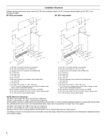
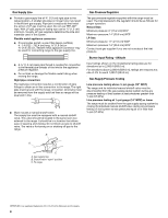
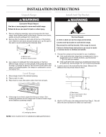
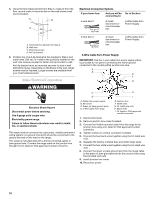
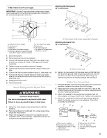
4. Using the final measurement from Step 3, measure from the floor up and mark a horizontal line on the wall where a wall stud is located. A B D C A. Horizontal line marked from Step 4. B. Wall stud C. Mounting screws D. Anti-tip bracket 5. Position top of anti-tip bracket at line marked in Step 4 and mark holes. Drill two ¹⁄₈" holes at the positions marked on the wall. Use screws provided to fasten anti-tip bracket to wall. Anti-tip bracket must be mounted securely to stud in wall behind the range. Depending on thickness of the wall, longer screws may be required. Longer screws are available from your local hardware store. Make Electrical Connection WARNING Electrical Shock Hazard Disconnect power before servicing. Use 8 gauge solid copper wire. Electrically ground range. Failure to follow these instructions can result in death, fire, or electrical shock. This range must be connected to a grounded, metallic permanent wiring system or a ground connector should be connected to the ground terminal or wire lead on the range. This range is manufactured with a frame connected, green or bare ground wire. Connect the range cable to the junction box through the UL listed or CSA approved conduit connector. Electrical Connection Options If your home has: And you will be connecting to: Go to Section: 4-wire direct 5" (12.7 cm) A fused disconnect or circuit breaker box 4-Wire Cable from Power Supply 3-wire direct 3¹⁄₂" (8.9 cm) A fused disconnect or circuit breaker box 3-Wire Cable from Power Supply 4-Wire Cable from Power Supply IMPORTANT: Use the 4-wire cable from power supply where local codes do not permit connecting the frame-ground conductor to the neutral (white) junction box wire. A B E F G C H D I A. Cable from power supply B. Red wires C. Green (or bare) ground wires D. 4-Wire cable from range E. Junction box F. White wires G. UL listed wire nuts H. Black wires I. UL listed or CSA approved conduit connector 1. Disconnect power. 2. Remove junction box cover if present. 3. Connect the flexible armored cable from the range to the junction box using a UL listed or CSA approved conduit connector. 4. Tighten screws on conduit connector if present. 5. Connect the two black wires together using the UL listed wire nuts. 6. Separate the factory-crimped bare and white range wires. 7. Connect the two white wires together using the UL listed wire nuts. 8. Connect the green or bare ground wire from the range cable to the green or bare grounded wire (in the junction box) using the UL listed wire nuts. 9. Install junction box cover. 10. Reconnect power. 10
-
 1
1 -
2
-
3
-
4
-
 5
5 -
 6
6 -
 7
7 -
 8
8 -
 9
9 -
 10
10 -
 11
11 -
 12
12 -
 13
13 -
 14
14 -
 15
15 -
16
 |
 |
