KitchenAid KDRP707RSS Installation Instructions - Page 11
Attach Backguard or Island Trim, Make Gas Connection, Wire Cable from Power Supply - parts manual
 |
View all KitchenAid KDRP707RSS manuals
Add to My Manuals
Save this manual to your list of manuals |
Page 11 highlights
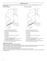
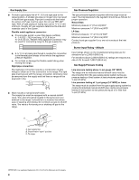
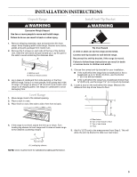
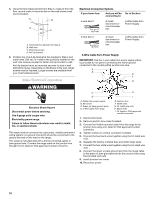
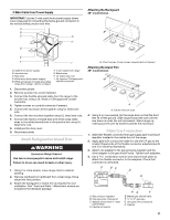
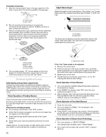
3-Wire Cable from Power Supply Attaching the Backguard 36" model shown IMPORTANT: Use the 3-wire cable from power supply where local codes permit connecting the frame-ground conductor to A the neutral (white) junction box wire. A B C G H D E F I A. Cable from power supply B. Junction box C. Red wires D. White wire (from power supply) E. White and green (or bare) grounding wires (from range) - factory crimped F. 4-wire cable from range G. Black wires H. UL listed wire nuts I. UL listed or CSA approved conduit connector 1. Disconnect power. 2. Remove junction box cover if present. 3. Connect the flexible armored cable from the range to the junction box using a UL listed or CSA approved conduit connector. 4. Tighten screws on conduit connector if present. 5. Connect the two black wires together using UL listed wire nuts. 6. Connect the two red wires together using UL listed wire nuts. 7. Connect the factory-crimped bare and white range cable wires to the white (neutral) wire in the junction box using UL listed wire nuts. 8. Install junction box cover. 9. Reconnect power. Attach Backguard or Island Trim WARNING Excessive Weight Hazard Use two or more people to move and install range. Failure to do so can result in back or other injury. 1. Using 2 or more people, move range close to cabinet opening. 2. Remove cardboard or hardboard from under range. Move range into final position. 3. Attach the backguard or island trim as required for your installation. See "Tools and Parts." Attachment screws are included in the literature package. A. 3 front screws (4 rear screws required but not shown) Attaching the Island Trim 36" model shown A A. Center hole not used 4. Using 2 or more people, tip the range back so that the front feet lift off the ground. Slide range toward the wall until the rear brace is under the anti-tip bracket. Stand range up, making sure the anti-tip bracket catches the rear brace. Make Gas Connection 1. Assemble flexible connector from gas supply pipe to pressure regulator located in the middle front of the range. 2. Apply pipe-joint compound made for use with LP gas to the smaller thread ends of the flexible connector adapters (see B and G in following illustration). 3. Attach one adapter to the gas pressure regulator and the other adapter to the gas shutoff valve. Tighten both adapters. 4. Use a combination wrench and channel lock pliers to attach the flexible connector to the adapters. Check that connector is not kinked. A BC D E A. Gas pressure regulator B. Use pipe-joint compound C. Adapter (must have ½" male pipe thread) D. Flexible connector HG F E. Manual gas shutoff valve F. ½" or ¾" gas pipe G. Use pipe-joint compound H. Adapter 11
-
 1
1 -
2
-
3
-
4
-
5
-
 6
6 -
 7
7 -
 8
8 -
 9
9 -
 10
10 -
 11
11 -
 12
12 -
 13
13 -
 14
14 -
 15
15 -
 16
16
 |
 |
