KitchenAid KDRP707RSS Installation Instructions - Page 4
INSTALLATION REQUIREMENTS, Tools and Parts, WARNING - range
 |
View all KitchenAid KDRP707RSS manuals
Add to My Manuals
Save this manual to your list of manuals |
Page 4 highlights
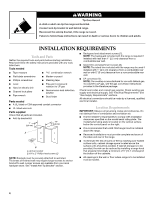
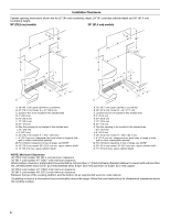
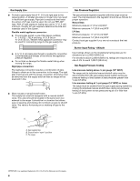
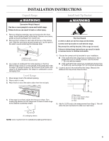
WARNING Tip Over Hazard A child or adult can tip the range and be killed. Connect anti-tip bracket to wall behind range. Reconnect the anti-tip bracket, if the range is moved. Failure to follow these instructions can result in death or serious burns to children and adults. INSTALLATION REQUIREMENTS Tools and Parts Gather the required tools and parts before starting installation. Read and follow the safety instructions provided with any tools listed here. Tools needed s Tape measure s combination wrench s Flat-blade screwdriver s Marker or pencil s Phillips screwdriver s Masking tape s Level s Hand or electric drill s Channel lock pliers s Pipe wrench s Pipe-joint compound resistant to LP gas s Noncorrosive leak-detection solution s Stud finder Parts needed s A UL listed or CSA approved conduit connector s UL listed wire nuts Parts supplied Check that all parts are included. s Anti-tip bracket kit 1" (2.5 cm) 1¾" (4.4 cm) A s Backguard and attachment screws (7). NOTE: The backguard included with the range is required if installed with less than 1" (2.5 cm) clearance from a combustible rear wall. s Island trim and attachment screws (3). NOTE: The island trim included with the range may be used if installed with 1" (2.5 cm) clearance from a combustible rear wall or with 0" (0 cm) clearance from a noncombustible rear wall. s LP conversion kit. NOTE: The cooktop is manufactured for use with Natural gas. To convert to LP gas, see the gas conversion instructions provided in the literature package. Check local codes and consult gas supplier. Check existing gas supply and electrical supply. See "Electrical Requirements" and "Gas Supply Requirements" sections. All electrical connections should be made by a licensed, qualified electrical installer. Location Requirements IMPORTANT: Observe all governing codes and ordinances. Do not obstruct flow of combustion and ventilation air. s It is the installer's responsibility to comply with installation clearances specified on the model/serial rating plate. The model/serial rating plate is located on the vertical surface below the control panel on the right. s It is recommended that a 600 CFM range hood be installed above the range. s Recessed installations must provide complete enclosure of the sides and rear of the range. B A. Anti-tip bracket B. #10 x 2" Phillips head screws (2) NOTE: Brackets must be securely attached to wall stud. Thickness of finished wall may require longer screws to anchor bracket to wall. Longer screws are available from your local hardware store. See "Install Anti-Tip Bracket" section. s To eliminate the risk of burns or fire by reaching over heated surface units, cabinet storage space located above the surface units should be avoided. If cabinet storage is to be provided, the risk can be reduced by installing a range hood that projects horizontally a minimum of 5" (12.7 cm) beyond the bottom of the cabinets. s All openings in the wall or floor where range is to be installed must be sealed. 4
-
 1
1 -
 2
2 -
 3
3 -
 4
4 -
 5
5 -
 6
6 -
 7
7 -
 8
8 -
 9
9 -
 10
10 -
11
-
12
-
13
-
14
-
15
-
16
 |
 |
