KitchenAid KECD866RWW Installation Instructions - Page 6
Electrical, requirements, connection, Installation
 |
UPC - 050946991665
View all KitchenAid KECD866RWW manuals
Add to My Manuals
Save this manual to your list of manuals |
Page 6 highlights
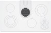
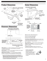
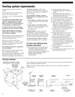
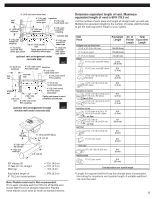
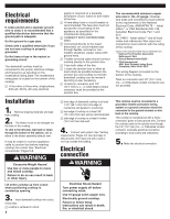
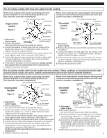
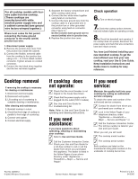
Electrical requirements If codes permit and a separate ground wire is used, it is recommended that a qualified electrician determine that the ground path is adequate. Do Not ground to a gas pipe. Check with a qualified electrician if you are not sure cooktop is properly grounded. Do Not have a fuse in the neutral or grounding circuit. The downdraft cooktop must be connected to the proper electrical voltage and frequency as specified on the model/serial rating plate. The model/serial rating plate is located on the bottom of the cooktop. ࠜ A four-wire or three-wire, single-phase, 240-volt, 60-Hz, AC-only electrical Installation 1. Remove shipping materials and tape from cooktop. 2. The blower is set to vent straight out the back of the cooktop. To vent to the left side, right side or down through the bottom of the cabinet, add an elbow to the blower assembly exhaust vent. It may be easier to connect appliance cable to junction box before inserting cooktop into cutout. See "Electrical connections," Pages 6-8. WARNING Excessive Weight Hazard Use two or more people to move and install cooktop. Failure to do so can result in back or other injury. Lift entire cooktop up from cutout when positioning cooktop in countertop opening. 3. Insert downdraft cooktop into cutout. Check that: cooktop is centered in cutout. 6 supply is required on a separate 30-ampere circuit, fused on both sides of the line. ࠜ A time-delay fuse or circuit breaker is recommended. The fuse size must not exceed the circuit rating of the appliance as specified on the model/serial rating plate. ࠜ CONNECT WITH COPPER WIRE ONLY. ࠜ Connected directly to the fused disconnect (or circuit breaker box) through flexible, armored or nonmetallic sheathed, copper cable (with ground wire). ࠜ Flexible armored cable should connect cooktop directly to the junction box. ࠜ Fuse both sides of the line. ࠜ Locate the junction box to allow as much slack as possible between the junction box and cooktop so that the downdraft cooktop can be moved if servicing is ever necessary. ࠜ A twist-on connector and 1/2" (12.7 mm) U.L.- or CSA-listed conduit connector must be provided at the junction box. front edge of downdraft cooktop is at least 1-1/2" (38.1 mm) from front edge of countertop and parallel to countertop. rear edge of cooktop is at least 3/4" (19.1 mm) from rear wall as recommended. side edge of cooktop is at least 6 inches (15.2 cm) from side wall. 4. Connect vent system. See "Venting requirements," Pages 4-5. Use duct tape to seal all joints. Vent must end with a wall or roof cap outside the building. Electrical connection WARNING Electrical Shock Hazard Turn power supply off before connecting wires. Use 10-gauge solid copper wire. Electrically ground cooktop. Failure to follow these instructions can result in death, fire, or electrical shock. The recommended minimum copper wire size is No.-10 gauge. However, wire sizes and connections must conform to the requirements of the National Electrical Code, ANSI/NFPA 70 - latest edition*, or CSA Standards C22.1-94, Canadian Electrical Code, Part 1 and 22.2 No. 0-M91 - latest edition** and all local codes and ordinances. Wire sizes and connections must conform with the rating of the cooktop. Copies of the standard listed may be obtained from: * National Fire Protection Association Batterymarch Park Quincy, Massachusetts 02269 ** CSA International 8501 East Pleasant Valley Road Cleveland, Ohio 44131-5575 The wiring diagram is located on the bottom of the cooktop. Twist-on connector and 1/2" (12.7 mm) U.L.- or CSA-listed conduit connector are not provided. This cooktop must be connected to a grounded, metallic permanent wiring system or a ground connector should be connected to the ground terminal or wire lead on the cooktop. This cooktop is manufactured with a frame connected, green or bare ground wire. Connect the cooktop cable to the junction box through the 1/2" (12.7 mm) U.L.- or CSA-listed conduit connector. Complete electrical connection according to local codes and ordinances. 5. Make the electrical connection:
-
 1
1 -
 2
2 -
 3
3 -
 4
4 -
 5
5 -
 6
6 -
 7
7 -
 8
8 -
 9
9 -
 10
10 -
 11
11 -
 12
12 -
13
-
14
-
15
-
16
-
17
-
18
-
19
-
20
 |
 |