KitchenAid KGCU463VSS Installation Guide - Page 10
Typical flexible connection, Complete Connection - cooktop
 |
UPC - 883049155975
View all KitchenAid KGCU463VSS manuals
Add to My Manuals
Save this manual to your list of manuals |
Page 10 highlights
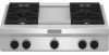
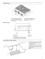
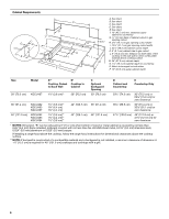
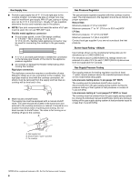
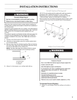
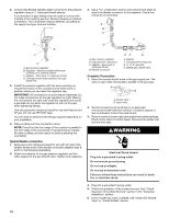
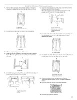
2. Connect the flexible stainless steel connector to the pressure regulator using a ¹⁄₂" male pipe thread adapter. A combination of pipe fittings must be used to connect the cooktop to the existing gas line. Shown following is a typical connection. Your connection may be different, according to the supply line type, size and location. 3. Use a combination wrench and channel lock pliers to attach the flexible connector to the adapters. Check that connector is not kinked. A B C A B C D A. Gas pressure regulator B. Regulator - Must be installed with arrow pointing up to cooktop bottom C. Adapter - Must have ¹⁄₂" male pipe thread D. CSA approved flexible stainless steel gas supply line 3. Install the pressure regulator with the arrow pointing up toward the bottom of the cooktop burner base and in a position where you can reach the regulator cap. IMPORTANT: All connections must be wrench-tightened. Do not make connections to the gas regulator too tight. Making the connections too tight may crack the regulator and cause a gas leak. Do not allow the regulator to turn on the pipe when tightening fittings. Use only pipe-joint compound made for use with Natural and LP gas. Do not use TEFLON® tape. You will need to determine the fittings required depending on your installation. 4. Place cooktop into the countertop cutout. NOTE: Check that the front edge of the cooktop is parallel to the front edge of the countertop. If repositioning is needed, lift entire cooktop up from cutout to avoid scratching the countertop. Typical flexible connection 1. Apply pipe-joint compound made for use with LP gas to the smaller thread ends of the flexible connector adapters (see B and F in the following illustration). 2. Attach one adapter to the gas pressure regulator and the other adapter to the gas shutoff valve. Tighten both adapters. H D A. Gas pressure regulator B. Use pipe-joint compound. C. Adapter - Must have ½" male pipe thread D. Flexible connector EF G E. Adapter F. Use pipe-joint compound. G. ½" or ¾" gas pipe H. Manual gas shutoff valve Complete Connection 1. Open the manual shutoff valve in the gas supply line. The valve is open when the handle is parallel to the gas pipe. A B A. Closed valve B. Open valve 2. Test all connections by brushing on an approved noncorrosive leak-detection solution. If bubbles appear, a leak is indicated. Correct any leak found. 3. Remove surface burner caps and grates from parts package. Place burner caps on burner bases. Place burner grates over burners and caps. WARNING Electrical Shock Hazard Plug into a grounded 3 prong outlet. Do not remove ground prong. Do not use an adapter. Do not use an extension cord. Failure to follow these instructions can result in death, fire, or electrical shock. 4. Plug into a grounded 3 prong outlet. 5. Check the operation of the surface burners. See "Check Operation of Cooktop Burners" section in the "Complete Installation" section. 6. If your model has a grill or griddle, see "Install Grill Grease Trays" or "Install Griddle" section. 10
-
 1
1 -
2
-
3
-
4
-
 5
5 -
 6
6 -
 7
7 -
 8
8 -
 9
9 -
 10
10 -
 11
11 -
 12
12 -
 13
13 -
 14
14 -
 15
15 -
16
-
17
-
18
-
19
-
20
-
21
-
22
-
23
-
24
-
25
-
26
-
27
-
28
-
29
-
30
-
31
-
32
-
33
-
34
-
35
-
36
-
37
-
38
-
39
-
40
 |
 |
