KitchenAid KGCU463VSS Installation Guide - Page 15
Replace Igniter - Small Surface Burners Only
 |
UPC - 883049155975
View all KitchenAid KGCU463VSS manuals
Add to My Manuals
Save this manual to your list of manuals |
Page 15 highlights
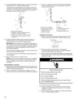
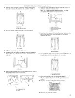
Medium Burner A A. Burner cap B. Burner head B C. Gas opening C D. Burner base D A Small Burner A. Burner cap B B. Burner head C. Gas opening C D. Burner base D 5. Apply masking tape to the end of a 7 mm nut driver to help hold the gas orifice spud in the nut driver while changing it. Insert nut driver into gas opening and press down onto the gas orifice spud and remove by turning the gas orifice spud counterclockwise and lifting out. Set gas orifice spud aside. 6. Replace with correct LP gas orifice spud. See the "LP Gas Orifice Spud/Hood Chart." Use the following chart to find the exact orifice spud placement. LP Gas Orifice Spud/Hood Chart Burner Rating Color Size Burner Style 3,000 BTU NA 0.65 mm Small burners Replace Igniter - Small Surface Burners Only 1. Unplug igniter wire from electrode. IMPORTANT: Do not let the igniter wire fall down under the cooktop surface. 2. Using needle-nose pliers, remove the retaining clip and spring from the igniter. AB C A. Retaining clip B. Spring C. Natural gas igniter 3. Remove Natural gas igniter from burner base. 4. Place spacer ring onto the LP gas igniter and insert into the burner base. A 12,500 BTU Blue 1.04 mm Medium burners 15,500 BTU Yellow 1.05 mm Large burner - main Green 0.45 mm Large burner - simmer A. Spacer 5. Insert new spring from LP conversion kit onto the underside of the igniter and lock into place with the new retaining clip. AB 14,500 BTU Black 1.18 mm Grill burner C Burner orifice spud Grill orifice hood A A A. Size stamp or color A. Size stamp 7. Place Natural gas orifice spuds in plastic parts bag for future use and keep with package containing literature. 8. For medium and large burners, replace the burner base using both screws. Replace burner head and cap. For small burners, replace igniter using the following instructions. A. Retaining clip B. Spring C. LP gas igniter 6. Place Natural gas igniter, spring, and clip in plastic parts bag for future use and keep with package containing literature. 7. Plug in igniter wire. 8. Replace the burner base using both screws. 9. Replace burner head and cap. 15
-
 1
1 -
2
-
3
-
4
-
5
-
6
-
7
-
8
-
9
-
 10
10 -
 11
11 -
 12
12 -
 13
13 -
 14
14 -
 15
15 -
 16
16 -
 17
17 -
 18
18 -
 19
19 -
 20
20 -
21
-
22
-
23
-
24
-
25
-
26
-
27
-
28
-
29
-
30
-
31
-
32
-
33
-
34
-
35
-
36
-
37
-
38
-
39
-
40
 |
 |
