KitchenAid KGSS907SBL Installation Instructions - Page 10
Adjust Leveling Legs, Install Anti-Tip Bracket
 |
UPC - 883049027517
View all KitchenAid KGSS907SBL manuals
Add to My Manuals
Save this manual to your list of manuals |
Page 10 highlights
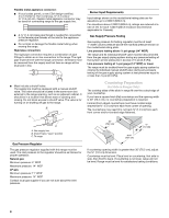
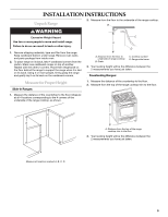
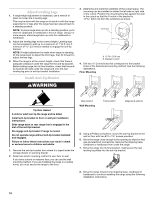
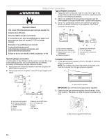
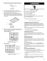
Adjust Leveling Legs 1. If range height adjustment is necessary, use a wrench or pliers to loosen the 4 leveling legs. This may be done with the range on its back or with the range supported on 2 legs after the range has been placed back to a standing position. NOTE: To place range back up into a standing position, put a sheet of cardboard or hardboard in front of range. Using 2 or more people, stand range back up onto the cardboard or hardboard. 2. Adjust the leveling legs to the correct height. Leveling legs can be loosened to add up to a maximum of 1" (2.5 cm). A minimum of 5.0 mm) is needed to engage the anti-tip bracket. NOTE: If height adjustment is made when range is standing, tilt the range back to adjust the front legs, then tilt forward to adjust the rear legs. 3. When the range is at the correct height, check that there is adequate clearance under the range for the anti-tip bracket. Before sliding range into its final location, check that the antitip bracket will slide under the range and onto the rear leveling leg prior to anti-tip bracket installation. Install Anti-Tip Bracket 3. Determine and mark the centerline of the cutout space. The mounting can be installed on either the left side or right side of the cutout. Position the mounting bracket against the wall in the cutout so that the V-notch in the bracket is 13 33.6 cm) from the centerline as shown. B Centerline A A. 13 33.6 cm) B. Bracket V-notch 4. Drill two ¹⁄₈" (3 mm) holes that correspond to the bracket holes of the determined mounting method. See the following illustrations. Floor Mounting WARNING Tip Over Hazard A child or adult can tip the range and be killed. Install anti-tip bracket to floor or wall per installation instructions. Slide range back so rear range foot is engaged in the slot of the anti-tip bracket. Re-engage anti-tip bracket if range is moved. Do not operate range without anti-tip bracket installed and engaged. Failure to follow these instructions can result in death or serious burns to children and adults. 1. Remove the anti-tip bracket from where it is taped inside the storage drawer or warming drawer. 2. Determine which mounting method to use: floor or wall. If you have a stone or masonry floor, you can use the wall mounting method. If you are installing the range in a mobile home, you must secure the range to the floor. Rear position Wall Mounting Front position Diagonal (2 options) 5. Using a Phillips screwdriver, mount the anti-tip bracket to the wall or floor with two #12 x 1⁵⁄₈" screws provided. 6. Move the range close enough to the opening to allow for final gas and electrical connections. Remove the shipping base, cardboard or hardboard from under the range. 7. Move the range into its final location, making sure the rear leveling leg slides into the anti-tip bracket. 8. Move the range forward onto shipping base, cardboard or hardboard to continue installing the range using the following installation instructions. 10
-
 1
1 -
2
-
3
-
4
-
 5
5 -
 6
6 -
 7
7 -
 8
8 -
 9
9 -
 10
10 -
 11
11 -
 12
12 -
 13
13 -
 14
14 -
 15
15 -
16
-
17
-
18
-
19
-
20
-
21
-
22
-
23
-
24
-
25
-
26
-
27
-
28
-
29
-
30
-
31
-
32
-
33
-
34
-
35
-
36
-
37
-
38
-
39
-
40
-
41
-
42
-
43
-
44
 |
 |
