KitchenAid KOSE500ESS Installation Guide - Page 15
Install Warming Drawer Deflector Kit Only, for Ovens Installed Above Warming, Drawers - installation guide
 |
View all KitchenAid KOSE500ESS manuals
Add to My Manuals
Save this manual to your list of manuals |
Page 15 highlights
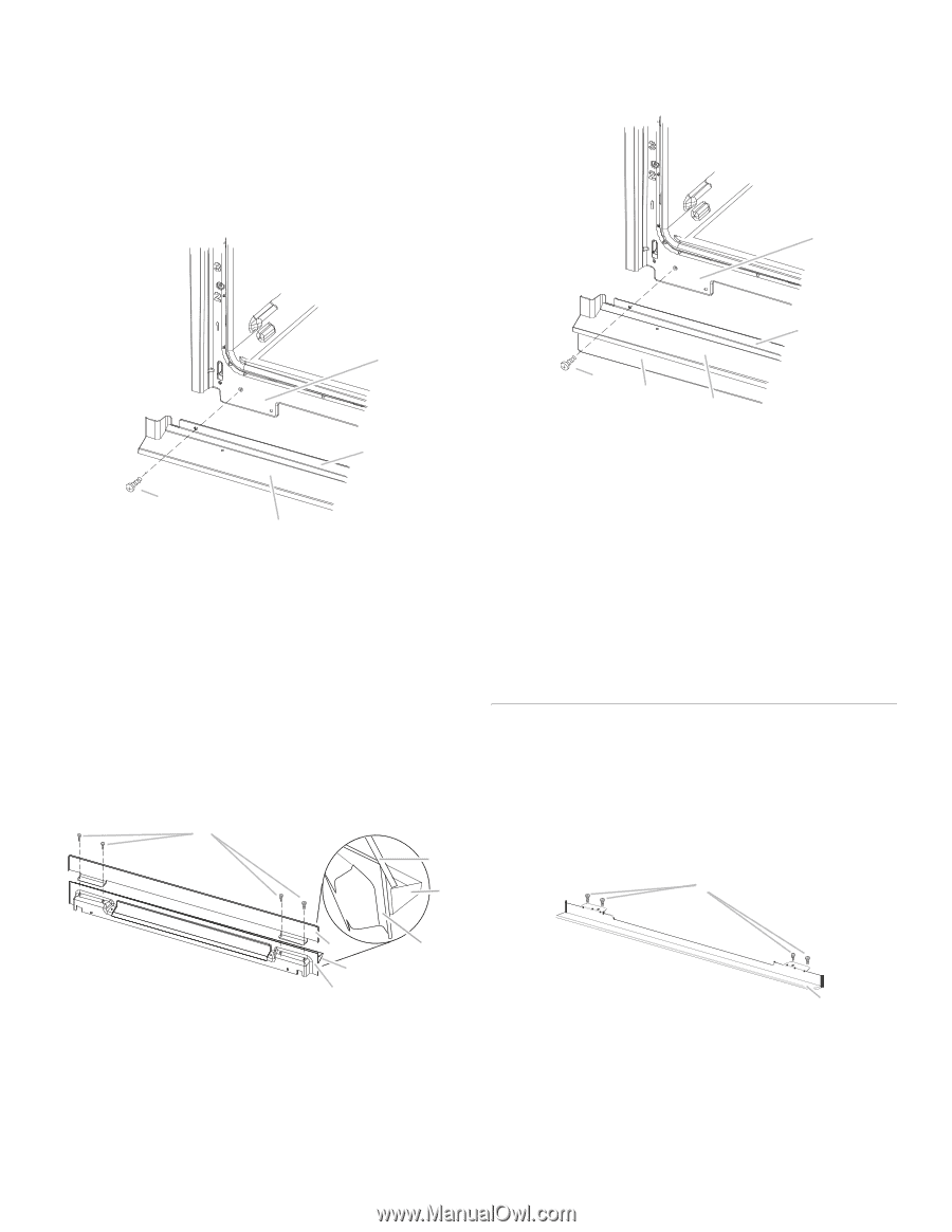
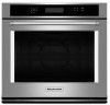
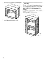
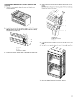
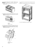
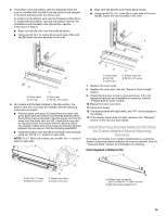
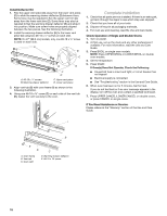
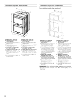
5. The bottom vent and bottom vent trim (required when the oven is installed with the feet in the tall position) are shipped in the foam packing at the top of the oven. To install only the bottom vent, see the following instructions. To install both the bottom vent and the bottom vent trim for installations with the feet in the tall position, see the instructions in Step 6. ■ Align vent tab (B) with oven frame (A) as shown. ■ Using one #8-18 x ³⁄₈" screw (D) on each side of the vent tab (B), fasten the vent securely to the oven. ■ Align vent tab (B) with oven frame (A) as shown. ■ Using one #8-18 x ³⁄₈" screw (E) on each side of the vent tab (B), fasten the vent securely to the oven. A A B D C A. Oven frame B. Vent tab C. Oven vent D. #8-18 x ³⁄₈" screws 6. On models with the feet installed in the tall position, the bottom vent trim must also be installed. See the following instructions to install. ■ Flex the upper vent piece (C) away from the lower vent piece (D) to slide the bottom vent trim (B) between them. Some force may be required to flex the upper vent trim (C) away from the lower vent trim (D). Some force may also be required to flex the bottom vent trim (B) and slide it into position. Make sure screw holes are properly aligned between the two pieces. See the following illustration. ■ Install the bottom vent trim (B) to the lower vent piece (D) using two #8-18 x ¹⁄₄" screws on each side. NOTE: On 27" (68.6 cm) models, only one #8-18 x ¹⁄₄" screw is used on each side. A B C B E D C A. Oven frame B. Vent tab C. Oven vent D. Bottom vent trim E. #8-18 x ³⁄₈" screw 7. Replace the oven racks. 8. Replace the oven door. See the "Replace Oven Door(s)" section. 9. Check that the door is free to open and close. If it is not, repeat the removal and installation procedures. See the "Prepare Built-In Oven" section. 10. Repeat for lower oven door. 11. Reconnect power. 12. The display panel will light briefly, and "PF" should appear in the display. 13. If the display panel does not light, reference the "Warranty" section of the Use and Care Guide. Install Warming Drawer Deflector Kit (Only for Ovens Installed Above Warming Drawers) On single and double oven models installed above a warming drawer, a warming drawer deflector kit must be installed. See the "Tools and Parts" section for information on ordering. Parts Supplied in Deflector Kit A B D C D A. #8-18 x ¹⁄₄" screw B. Bottom vent trim C. Upper vent piece D. Lower vent piece B A. Phillips head screws (4) only 2 screws for 27" (68.6 cm) size B. Warming drawer deflector (1) 15
-
 1
1 -
2
-
3
-
4
-
5
-
6
-
7
-
8
-
9
-
 10
10 -
 11
11 -
 12
12 -
 13
13 -
 14
14 -
 15
15 -
 16
16 -
 17
17 -
 18
18 -
 19
19 -
 20
20 -
21
-
22
-
23
-
24
-
25
-
26
-
27
-
28
-
29
-
30
-
31
-
32
 |
 |