Kyocera 1030DN Operation Guide - Page 25
Machine Parts
 |
View all Kyocera 1030DN manuals
Add to My Manuals
Save this manual to your list of manuals |
Page 25 highlights
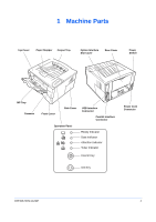
1 Machine Parts Top Cover Paper Stopper Output Tray Option Interface Slot Cover Rear Cover Power Switch MP Tray Cassette Front Cover Side Cover USB Interface Connector Parallel Interface Connector Operation Panel Ready Indicator Data Indicator Attention Indicator Toner Indicator Cancel Key Power Cord Connector GO Key OPERATION GUIDE 1
-
 1
1 -
2
-
3
-
4
-
5
-
6
-
7
-
8
-
9
-
10
-
11
-
12
-
13
-
14
-
15
-
16
-
17
-
18
-
19
-
 20
20 -
 21
21 -
 22
22 -
 23
23 -
 24
24 -
 25
25 -
 26
26 -
 27
27 -
 28
28 -
 29
29 -
 30
30 -
31
-
32
-
33
-
34
-
35
-
36
-
37
-
38
-
39
-
40
-
41
-
42
-
43
-
44
-
45
-
46
-
47
-
48
-
49
-
50
-
51
-
52
-
53
-
54
-
55
-
56
-
57
-
58
-
59
-
60
-
61
-
62
-
63
-
64
-
65
-
66
 |
 |

OPERATION GUIDE
1
1
Machine Parts
Top Cover
Output Tray
MP Tray
Power
Switch
Parallel Interface
Connector
USB Interface
Connector
Cassette
Rear Cover
Side Cover
Paper Stopper
Operation Panel
Ready Indicator
Data Indicator
Attention Indicator
Toner Indicator
Cancel Key
GO Key
Power Cord
Connector
Option Interface
Slot Cover
Front Cover