Kyocera FS 1010 FS-1010 Operation Guide Rev-1.2 - Page 75
B.3 Serial Interface (Option), B.3.1 RS-232C Interface, B.3.1
 |
View all Kyocera FS 1010 manuals
Add to My Manuals
Save this manual to your list of manuals |
Page 75 highlights
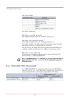
Serial Interface (Option) B.3 Serial Interface (Option) Installing the optional serial interface board kit (IB-10E) in the printer enables connection to a computer with an RS-232C or RS-422A standard serial interface. B.3.1 RS-232C Interface Interface Signals The pins of the printer's RS-232C interface connector carry the signals listed in Table B.3. The table also indicates whether each signal is incoming or outgoing with respect to the printer. Table B.3 RS-232C Signal Pin Assignments Pin In/out Signal Description 1 - FG Frame ground 2 Out TXD Transmit Data 3 In RXD Receive Data 4 Out RTS Request To Send 5 In CTS Clear To Send 6 In DSR Data Set Ready 7 - SG Signal Ground 20 Out DTR Data Terminal Ready Brief descriptions of the signals follow. FG - Frame Ground - (Pin 1) This pin is connected directly to the printer frame. TXD - Transmit Data - (Pin 2) This output carries asynchronous data sent by the printer to the computer. It is used mainly in handshaking protocols. RXD - Receive Data - (Pin 3) This input carries serial asynchronous data sent by the computer to the printer. RTS - Request To Send - (Pin 4) This output is always held high (above 3 volts). CTS - Clear To Send - (Pin 5) DSR - Data Set Ready - (Pin 6) Unused. B-7
-
 1
1 -
2
-
3
-
4
-
5
-
6
-
7
-
8
-
9
-
10
-
11
-
12
-
13
-
14
-
15
-
16
-
17
-
18
-
19
-
20
-
21
-
22
-
23
-
24
-
25
-
26
-
27
-
28
-
29
-
30
-
31
-
32
-
33
-
34
-
35
-
36
-
37
-
38
-
39
-
40
-
41
-
42
-
43
-
44
-
45
-
46
-
47
-
48
-
49
-
50
-
51
-
52
-
53
-
54
-
55
-
56
-
57
-
58
-
59
-
60
-
61
-
62
-
63
-
64
-
65
-
66
-
67
-
68
-
69
-
 70
70 -
 71
71 -
 72
72 -
 73
73 -
 74
74 -
 75
75 -
 76
76 -
 77
77 -
 78
78 -
 79
79 -
 80
80 -
81
-
82
-
83
-
84
-
85
-
86
-
87
-
88
-
89
-
90
-
91
-
92
-
93
 |
 |
