Kyocera FS-1300DN Service Manual - Page 107
Electrical Parts Layout, 2-2-1 Electrical parts layout, (1) PWBs
 |
View all Kyocera FS-1300DN manuals
Add to My Manuals
Save this manual to your list of manuals |
Page 107 highlights
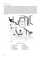
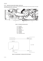
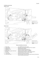
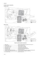
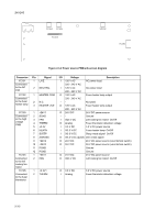
2-2 Electrical Parts Layout 2-2-1 Electrical parts layout (1) PWBs Simplex model 1 5 6 4 8 7 2H5/2HS 3 2 Duplex model 1 5 4 6 8 7 Machine left Machine inside Machine right 3 Machine left Machine inside 2 Machine right Figure 2-2-1 PWBs 1. Control PWB Main controller: Controls the software such as the print data processing and provides the interface with computers. Engine: Controls printer hardware such as high voltage/bias output control, paper conveying system control, and fuser temperature control, etc. 2. Power source PWB After full-wave rectification of AC power source input, switching for converting to 24 V DC for output. Controls the fuser heater lamp. 3. High voltage PWB Generates main charging, developing bias and transfer bias. 4. Operation panel PWB Consists the LED indicators and key switches. 5. APC PWB Generates and controls the laser beam. 2-2-1
-
 1
1 -
2
-
3
-
4
-
5
-
6
-
7
-
8
-
9
-
10
-
11
-
12
-
13
-
14
-
15
-
16
-
17
-
18
-
19
-
20
-
21
-
22
-
23
-
24
-
25
-
26
-
27
-
28
-
29
-
30
-
31
-
32
-
33
-
34
-
35
-
36
-
37
-
38
-
39
-
40
-
41
-
42
-
43
-
44
-
45
-
46
-
47
-
48
-
49
-
50
-
51
-
52
-
53
-
54
-
55
-
56
-
57
-
58
-
59
-
60
-
61
-
62
-
63
-
64
-
65
-
66
-
67
-
68
-
69
-
70
-
71
-
72
-
73
-
74
-
75
-
76
-
77
-
78
-
79
-
80
-
81
-
82
-
83
-
84
-
85
-
86
-
87
-
88
-
89
-
90
-
91
-
92
-
93
-
94
-
95
-
96
-
97
-
98
-
99
-
100
-
101
-
 102
102 -
 103
103 -
 104
104 -
 105
105 -
 106
106 -
 107
107 -
 108
108 -
 109
109 -
 110
110 -
 111
111 -
 112
112 -
113
-
114
-
115
-
116
-
117
-
118
-
119
-
120
-
121
-
122
-
123
-
124
 |
 |
