Kyocera FS-1300DN Service Manual - Page 74
(2) Detaching and refitting the power source PWB, Connector, YC104, Power source PWB, assembly
 |
View all Kyocera FS-1300DN manuals
Add to My Manuals
Save this manual to your list of manuals |
Page 74 highlights
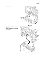
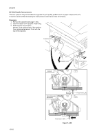
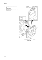
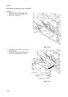
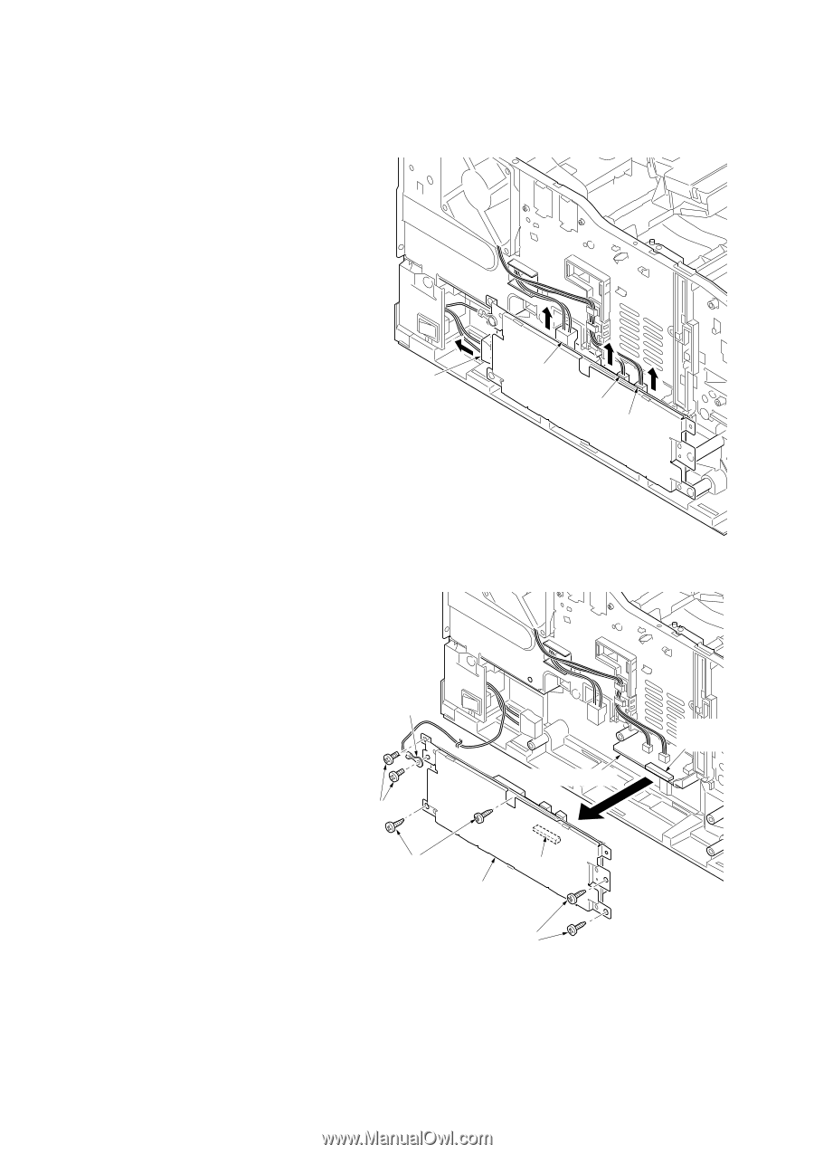
2H5/2HS (2) Detaching and refitting the power source PWB Procedure 1. Remove the top cover (See page 1-5-3). 2. Remove the left cover (See page 1-5-4). 3. Remove four connectors. Connector Connector Connector Connector (YC104) 4. Remove four P tight screws, two screws and ground terminal. 5. Remove the power source PWB assembly from the high voltage PWB's connector. Ground terminal Figure 1-5-30 Screws High voltage PWB P tight screws Power source PWB assembly Connector (YC103) P tight screws Figure 1-5-31 Connector (YC201) 1-5-22
-
 1
1 -
2
-
3
-
4
-
5
-
6
-
7
-
8
-
9
-
10
-
11
-
12
-
13
-
14
-
15
-
16
-
17
-
18
-
19
-
20
-
21
-
22
-
23
-
24
-
25
-
26
-
27
-
28
-
29
-
30
-
31
-
32
-
33
-
34
-
35
-
36
-
37
-
38
-
39
-
40
-
41
-
42
-
43
-
44
-
45
-
46
-
47
-
48
-
49
-
50
-
51
-
52
-
53
-
54
-
55
-
56
-
57
-
58
-
59
-
60
-
61
-
62
-
63
-
64
-
65
-
66
-
67
-
68
-
 69
69 -
 70
70 -
 71
71 -
 72
72 -
 73
73 -
 74
74 -
 75
75 -
 76
76 -
 77
77 -
 78
78 -
 79
79 -
80
-
81
-
82
-
83
-
84
-
85
-
86
-
87
-
88
-
89
-
90
-
91
-
92
-
93
-
94
-
95
-
96
-
97
-
98
-
99
-
100
-
101
-
102
-
103
-
104
-
105
-
106
-
107
-
108
-
109
-
110
-
111
-
112
-
113
-
114
-
115
-
116
-
117
-
118
-
119
-
120
-
121
-
122
-
123
-
124
 |
 |
2H5/2HS
1-5-22
(2) Detaching and refitting the power source PWB
Procedure
1.
Remove the top cover (See page 1-5-3).
2.
Remove the left cover (See page 1-5-4).
3.
Remove four connectors.
Figure 1-5-30
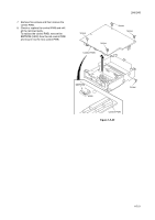
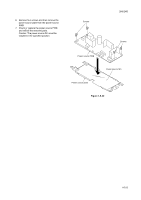
4.
Remove four P tight screws, two screws and
ground terminal.
5.
Remove the power source PWB assembly
from the high voltage PWB’s connector.
Figure 1-5-31
Connector
Connector
Connector
Connector
(YC104)
Power source PWB
assembly
P tight screws
P tight screws
Ground
terminal
Screws
Connector
(YC201)
High voltage PWB
Connector
(YC103)