Kyocera FS-1300DN Service Manual - Page 51
Problem, Causes, Check procedures/corrective measures, the paper feed/con
 |
View all Kyocera FS-1300DN manuals
Add to My Manuals
Save this manual to your list of manuals |
Page 51 highlights
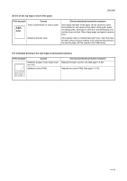
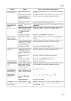
2H5/2HS Problem Causes Check procedures/corrective measures (6)developing clutch Broken developing clutch does not operate. coil. Check for continuity across the coil. If none, replace the developing clutch. Defective harness between developing clutch and control PWB (YC308), or improper connector insertion. Reinsert the connector. Also check for continuity within the connector harness. If none, remedy or replace the harness. Defective control PWB. Replace the control PWB (See page 1-5-19). (7)MP paper feed solenoid does not operate. (Duplex model only) Broken MP paper feed sole- Check for continuity across the coil. If none, replace the MP paper noid coil. feed solenoid. Defective harness between MP paper feed solenoid and control PWB (YC309), or improper connector insertion. Reinsert the connector. Also check for continuity within the connector harness. If none, remedy or replace the harness. Defective control PWB. Replace the control PWB (See page 1-5-19). (8)Duplex solenoid does not operate. (Duplex model only) Broken duplex solenoid coil. Check for continuity across the coil. If none, replace the duplex solenoid. Defective harness between duplex solenoid and control PWB (YC317), or improper connector insertion. Reinsert the connector. Also check for continuity within the connector harness. If none, remedy or replace the harness. Defective control PWB. Replace the control PWB (See page 1-5-19). (9)Eraser lamp does not turn on. Defective harness between eraser lamp (YC701) and control PWB (YC316), or improper connector insertion. Reinsert the connector. Also check for continuity within the connector harness. If none, remedy or replace the harness. Defective eraser lamp (PWB). Replace the eraser lamp (PWB) (See page 1-5-32). Defective control PWB. Replace the control PWB (See page 1-5-19). (10)Paper indicator is flashing when paper is present in the cassette. Defective paper sensor. Defective harness between paper sensor and control PWB (YC306), or improper connector insertion. Replace the paper sensor. Reinsert the connector. Also check for continuity within the connector harness. If none, remedy or replace the harness. (11)A paper jam in the paper feed/conveying section or fuser section is indicated when the power switch is turned on. A piece of paper torn from paper is caught around registration sensor or exit sensor. Check and remove if any. Defective registration sensor on the high voltage PWB. Replace the high voltage PWB (See page 1-5-25). Defective exit sensor. Replace the exit sensor. (12)Attention indica- Defective interlock switch Check for continuity across the interlock switch. If there is no con- tor is lit when the top on the power source PWB. tinuity when the interlock switch is on, replace the power source cover is closed. PWB (See page 1-5-22). 1-4-15
-
 1
1 -
2
-
3
-
4
-
5
-
6
-
7
-
8
-
9
-
10
-
11
-
12
-
13
-
14
-
15
-
16
-
17
-
18
-
19
-
20
-
21
-
22
-
23
-
24
-
25
-
26
-
27
-
28
-
29
-
30
-
31
-
32
-
33
-
34
-
35
-
36
-
37
-
38
-
39
-
40
-
41
-
42
-
43
-
44
-
45
-
 46
46 -
 47
47 -
 48
48 -
 49
49 -
 50
50 -
 51
51 -
 52
52 -
 53
53 -
 54
54 -
 55
55 -
 56
56 -
57
-
58
-
59
-
60
-
61
-
62
-
63
-
64
-
65
-
66
-
67
-
68
-
69
-
70
-
71
-
72
-
73
-
74
-
75
-
76
-
77
-
78
-
79
-
80
-
81
-
82
-
83
-
84
-
85
-
86
-
87
-
88
-
89
-
90
-
91
-
92
-
93
-
94
-
95
-
96
-
97
-
98
-
99
-
100
-
101
-
102
-
103
-
104
-
105
-
106
-
107
-
108
-
109
-
110
-
111
-
112
-
113
-
114
-
115
-
116
-
117
-
118
-
119
-
120
-
121
-
122
-
123
-
124
 |
 |
