LG 32LX4DC User Manual - Page 20
PC Setup - vesa
 |
View all LG 32LX4DC manuals
Add to My Manuals
Save this manual to your list of manuals |
Page 20 highlights
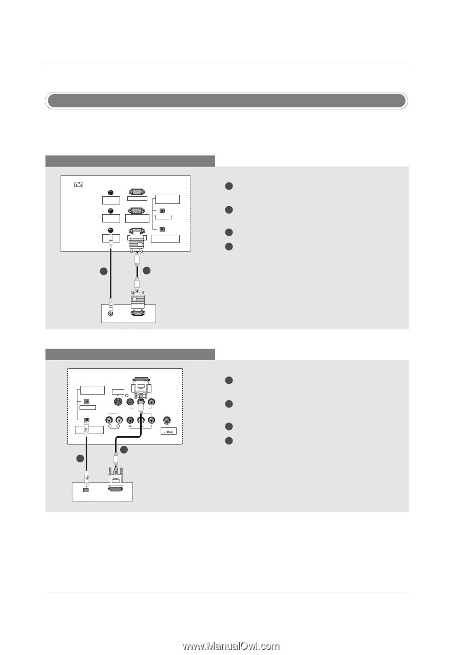
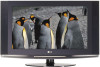
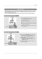
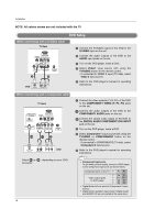
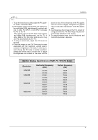
Installation PC Setup - This TV provides Plug and Play capability, meaning that the PC adjusts automatically to the TV's settings. The TV sends configuration information (EDID) to the PC using the Video Electronics Standard Association (VESA) Display Data Channel (DDC) protocol. When connecting with a D-sub 15 pin cable AC IN PC AUDIO INPUT2 PC INPUT2 DIGITAL AUDIO (OPTICAL) SPEAKER OUT RS-232C INPUT (CONTROL/SERVICE) OUTPUT PC AUDIO INPUT1 PC INPUT1 COMPONENT1/DVI INPUT TV Back 2 1 1 Connect the RGB output of the PC to the PC INPUT1 jack on the set. 2 Connect the PC audio outputs to the PC AUDIO INPUT1 jack on the set. 3 Turn on the PC and the set. 4 Select RGB1-PC input source in main input option of SETUP menu. (Refer to P.28) AUDIO RGB-PC OUTPUT PC When connecting with a DVI cable DIGITAL AUDIO (OPTICAL) DVI INPUT S-VIDEO (PC/DTV INPUT) R AUDIO L/MONO VIDEO OUTPUT VIDEO1 COMPONENT1 COMPONENT1/DVI R L INPUT AUDIO INPUT VIDEO INPUT Antenna 1 TV Back 2 DIGITAL AUDIO OPTICAL DVI-PC OUTPUT PC 1 Connect the DVI output of the PC to the DVI INPUT (PC/DTV INPUT) jack on the set. 2 Connect the PC audio outputs to the DIGITAL AUDIO COMPONENT1/DVI INPUT jack on the set. 3 Turn on the PC and the set. 4 Select DVI-PC input source in main input option of SETUP menu. (Refer to P.28) 20
-
 1
1 -
2
-
3
-
4
-
5
-
6
-
7
-
8
-
9
-
10
-
11
-
12
-
13
-
14
-
 15
15 -
 16
16 -
 17
17 -
 18
18 -
 19
19 -
 20
20 -
 21
21 -
 22
22 -
 23
23 -
 24
24 -
 25
25 -
26
-
27
-
28
-
29
-
30
-
31
-
32
-
33
-
34
-
35
-
36
-
37
-
38
-
39
-
40
-
41
-
42
-
43
-
44
-
45
-
46
-
47
-
48
-
49
-
50
-
51
-
52
-
53
-
54
-
55
-
56
-
57
-
58
-
59
-
60
 |
 |