LG 55LH90 Owner's Manual (English) - Page 11
Back Panel Information - audio output
 |
UPC - 719192174672
View all LG 55LH90 manuals
Add to My Manuals
Save this manual to your list of manuals |
Page 11 highlights
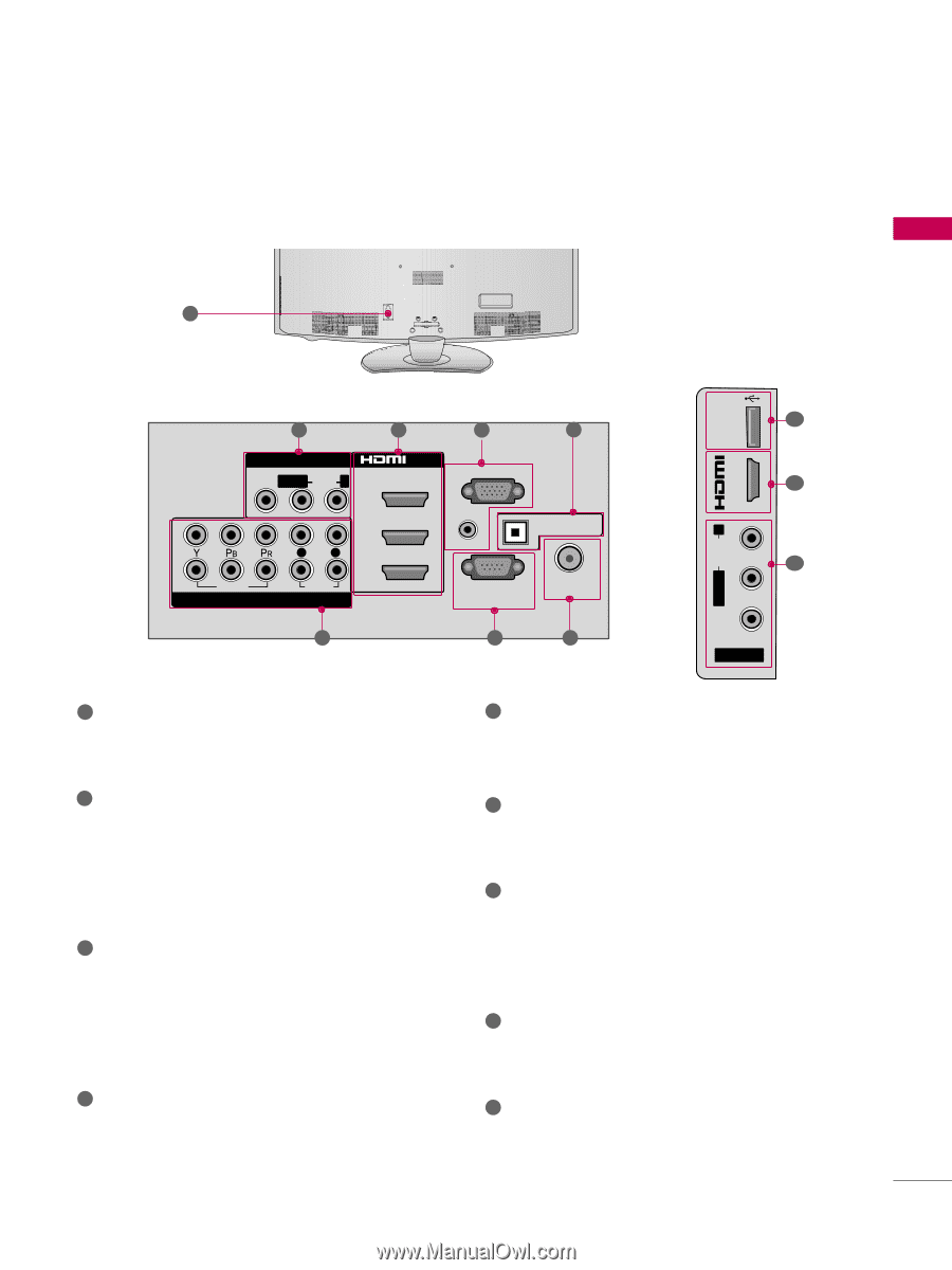
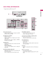
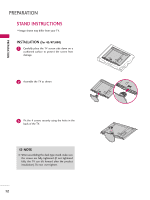
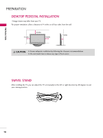
BACK PANEL INFORMATION I Image shown may differ from your TV. R PREPARATION 9 USB IN IN 4 1 2 3 4 AV IN 1 VIDEO L(MONO) AUDIO R 3 2 2 L R 1 1 VIDEO AUDIO COMPONENT IN /DVI IN RGB IN (PC) AUDIO IN (RGB/DVI) OPTICAL DIGITAL AUDIO OUT RS-232C IN ANTENNA/ CABLE IN (CONTROL&SERVICE) 7 6 5 VIDEO L/MONO AUDIO R 8 ( ) 2 1 ( ) AV IN 2 1 AV (Audio/Video) IN Analog composite connection. Supports standard definition video only (480i). 2 HDMI/DVI IN, HDMI IN Digital Connection. Supports HD video and Digital audio. Doesn't support 480i. Accepts DVI video using an adapter or HDMI to DVI cable (not included). 3 RGB IN (PC) Analog PC Connection. Uses a D-sub 15 pin cable (VGA cable). AUDIO IN (RGB/DVI) 1/8" (0.32 cm) headphone jack for analog PC audio input. 4 OPTICAL DIGITAL AUDIO OUT Digital optical audio output for use with amps and home theater systems. Note: In standby mode, this port doesn't work. 5 ANTENNA/CABLE IN Connect over-the air signals to this jack. Connect cable signals to this jack. ( ) 6 RS-232C IN (CONTROL & SERVICE) PORT Used by third party devices. This port is used for Service or Hotel mode. 7 COMPONENT IN Analog Connection. Supports HD. Uses a red, green, and blue cable for video & red and white for audio. 8 USB IN Used for viewing photos/movies and listening to MP3s. 9 Power Cord Socket For operation with AC power. Caution: Never attempt to operate the TV on DC power. ( ( 11
-
 1
1 -
2
-
3
-
4
-
5
-
 6
6 -
 7
7 -
 8
8 -
 9
9 -
 10
10 -
 11
11 -
 12
12 -
 13
13 -
 14
14 -
 15
15 -
 16
16 -
17
-
18
-
19
-
20
-
21
-
22
-
23
-
24
-
25
-
26
-
27
-
28
-
29
-
30
-
31
-
32
-
33
-
34
-
35
-
36
-
37
-
38
-
39
-
40
-
41
-
42
-
43
-
44
-
45
-
46
-
47
-
48
-
49
-
50
-
51
-
52
-
53
-
54
-
55
-
56
-
57
-
58
-
59
-
60
-
61
-
62
-
63
-
64
-
65
-
66
-
67
-
68
-
69
-
70
-
71
-
72
-
73
-
74
-
75
-
76
-
77
-
78
-
79
-
80
-
81
-
82
-
83
-
84
-
85
-
86
-
87
-
88
-
89
-
90
-
91
-
92
-
93
-
94
-
95
-
96
-
97
-
98
-
99
-
100
-
101
-
102
-
103
-
104
-
105
-
106
-
107
-
108
-
109
-
110
-
111
-
112
-
113
-
114
-
115
-
116
-
117
-
118
-
119
-
120
-
121
-
122
-
123
-
124
-
125
-
126
-
127
-
128
-
129
-
130
-
131
-
132
-
133
-
134
 |
 |