LG 60PC1D Owners Manual - Page 19
VCR Setup - service manual
 |
UPC - 719192170421
View all LG 60PC1D manuals
Add to My Manuals
Save this manual to your list of manuals |
Page 19 highlights
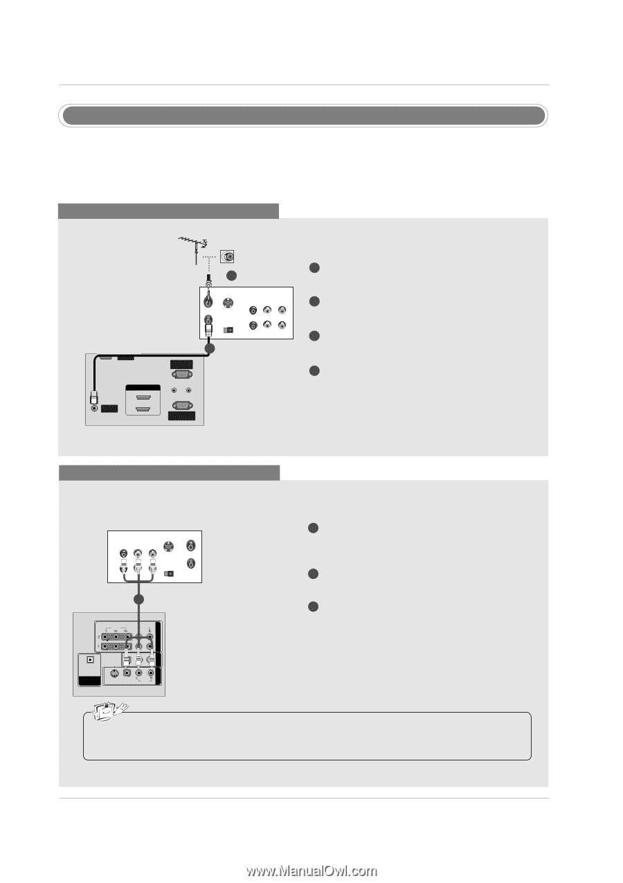
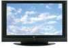
Installation VCR Setup - To avoid picture noise (interference), leave an adequate distance between the VCR and TV. - Typically a frozen still picture from a VCR. If the 4:3 picture format is used; the fixed images on the sides of the screen may remain visible on the screen. When connecting with an antenna 2 VCR ANT IN ANT OUT S-VIDEO OUT OUTPUT SWITCH 34 (R) AUDIO (L) IN VIDEO SERVICE 1 RGB IN (PC) ANTENNA/ CABLSEEIRNVICE HDMI IN 2 1(DVI) AUDIO IN REMOTE (RGB/DVI) CONTROL IN RGBRISN-232C IN ((CPOCN)TROL & SERVICE) AUDIO IN REMOTE (RGB/DVI) CONTROL IN HDMI / DVI IN ANTENNA/ CABLE IN RS-232C IN When connecting with a (CONTROL&SERVICE) RCA cable 1 Connect the RF antenna out socket of the VCR to the Antenna socket on the set. 2 Connect the antenna cable to the RF antenna in socket of the VCR. 3 Set VCR output switch to 3 or 4 and then tune TV to the same channel number. 4 Insert a video tape into the VCR and press PLAY on the VCR. (Refer to the VCR owner's manual.) VCR ANT IN OUT S-VIDEO (R) AUDIO (L) VIDEO OUTPUT SWITCH IN 34 VIDEO AUDIO ANT OUT 1 OPTICAL DIGITAL AUDIO ( ) VIDEOS-VIDEO VIDEOAUDIO AUDIO OUT 1 Connect the AUDIO/VIDEO jacks between TV and VCR. Match the jack colors (Video = yellow, Audio Left = white, and Audio Right = red) 2 Insert a video tape into the VCR and press PLAY on the VCR. (Refer to the VCR owner's manual.) 3 Select AV1 input source using the INPUT button on the remote control. - If connected to AV IN2, select AV2 input source. COMPONENT IN AV OUT AV IN 1 COMPONENT IN AV OUT AV IN 1 OPTICAL DIGITAL AUDIO OUT S-VIDEO VIDEO (MONO) AUDIO • If you have a mono VCR, connect the audio cable from the VCR to the AUDIO L/MONO jack of the set. VIDEO AUDIO OPTICAL DIGITAL AUDIO VIDEOS-VIDEO OUT ( ) VIDAEUODIO AUDIO 19 COMPONENT IN AV OUT AV IN 1 COMPONENT IN AV OUT A
-
 1
1 -
2
-
3
-
4
-
5
-
6
-
7
-
8
-
9
-
10
-
11
-
12
-
13
-
 14
14 -
 15
15 -
 16
16 -
 17
17 -
 18
18 -
 19
19 -
 20
20 -
 21
21 -
 22
22 -
 23
23 -
 24
24 -
25
-
26
-
27
-
28
-
29
-
30
-
31
-
32
-
33
-
34
-
35
-
36
-
37
-
38
-
39
-
40
-
41
-
42
-
43
-
44
-
45
-
46
-
47
-
48
-
49
-
50
-
51
-
52
-
53
-
54
-
55
-
56
-
57
-
58
-
59
-
60
-
61
-
62
-
63
-
64
-
65
-
66
-
67
-
68
 |
 |