LG DLE2140W Owner's Manual - Page 14
LG DLE2140W Manual
 |
UPC - 048231011402
View all LG DLE2140W manuals
Add to My Manuals
Save this manual to your list of manuals |
Page 14 highlights
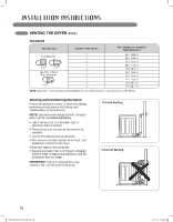
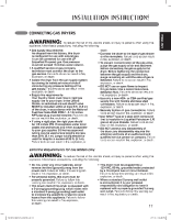
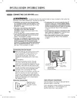
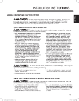
CHANGING THE DRYER vENT LOCATION wWARNING • Use a heavy metal vent. • Do not use plastic or thin foil duct. • Clean old ducts before installing this dryer. • o reduce the risk of personal injury, adhere to all T industry recommended safety procedures including the use of long sleeved gloves and safety glasses. • ailure to follow all of the safety warnings in this F manual could result in property damage, personal injury or death. Retaining Screw Rear Exhaust Duct An adapter kit, part number 383EEL9001B, may be purchased from your LG retailer. This kit contains the necessary duct components to change the dryer vent location. 1 Remove the rear exhaust duct retaining screw. Pull out the exhaust duct. OPTION 1: Side venting Adapter duct OPTION 2: Bottom venting Adapter Duct Bracket Knockout Bracket 2 Press the tabs on the knockout and carefully remove the knockout for the desired vent opening (right-side venting is not available on gas models). Press the adapter duct onto the blower housing and secure to the base of the dryer as shown. 2 Press the adapter duct onto the blower housing and secure to the base of the dryer as shown. Cover Plate Elbow 11/2" (3.8 cm) Cover Plate Elbow 3 Preassemble a 4 inches (10 cm) elbow to the next 4 inches (10 cm) duct section, and secure all joints with duct tape. Be sure that the male end of the elbow faces AWAY from the dryer. Insert the elbow/duct assembly through the side opening and press it onto the adapter duct. Secure in place with duct tape. Be sure that the male end of the duct protrudes 1½ inches (3.8 cm) to connect the remaining ductwork. Attach cover plate to the back of the dryer with included screw. 3 Insert the 4 inches (10 cm) elbow through the rear opening and press it onto the adapter duct. Be sure that the male end of the elbow faces down through hole in the bottom of the dryer. Secure in place with duct tape. Attach the cover plate to the back of the dryer with included screw. 14 MFL62512832_EN_100720.indd 14 7/21/10 1:55:46 PM
-
 1
1 -
2
-
3
-
4
-
5
-
6
-
7
-
8
-
 9
9 -
 10
10 -
 11
11 -
 12
12 -
 13
13 -
 14
14 -
 15
15 -
 16
16 -
 17
17 -
 18
18 -
 19
19 -
20
-
21
-
22
-
23
-
24
-
25
-
26
-
27
-
28
-
29
-
30
-
31
-
32
-
33
-
34
-
35
-
36
-
37
-
38
-
39
-
40
-
41
-
42
-
43
-
44
-
45
-
46
-
47
-
48
-
49
-
50
-
51
-
52
-
53
-
54
-
55
-
56
-
57
-
58
-
59
-
60
-
61
-
62
-
63
-
64
-
65
-
66
-
67
-
68
-
69
-
70
-
71
-
72
-
73
-
74
-
75
-
76
-
77
-
78
-
79
-
80
-
81
-
82
-
83
-
84
-
85
-
86
-
87
-
88
-
89
-
90
-
91
-
92
-
93
-
94
-
95
-
96
-
97
-
98
-
99
-
100
-
101
-
102
-
103
-
104
-
105
-
106
-
107
-
108
-
109
-
110
-
111
-
112
-
113
-
114
-
115
-
116
-
117
-
118
-
119
-
120
-
121
-
122
-
123
-
124
 |
 |
