LG DLG5988WM Service Manual - Page 22
Test 2
 |
View all LG DLG5988WM manuals
Add to My Manuals
Save this manual to your list of manuals |
Page 22 highlights
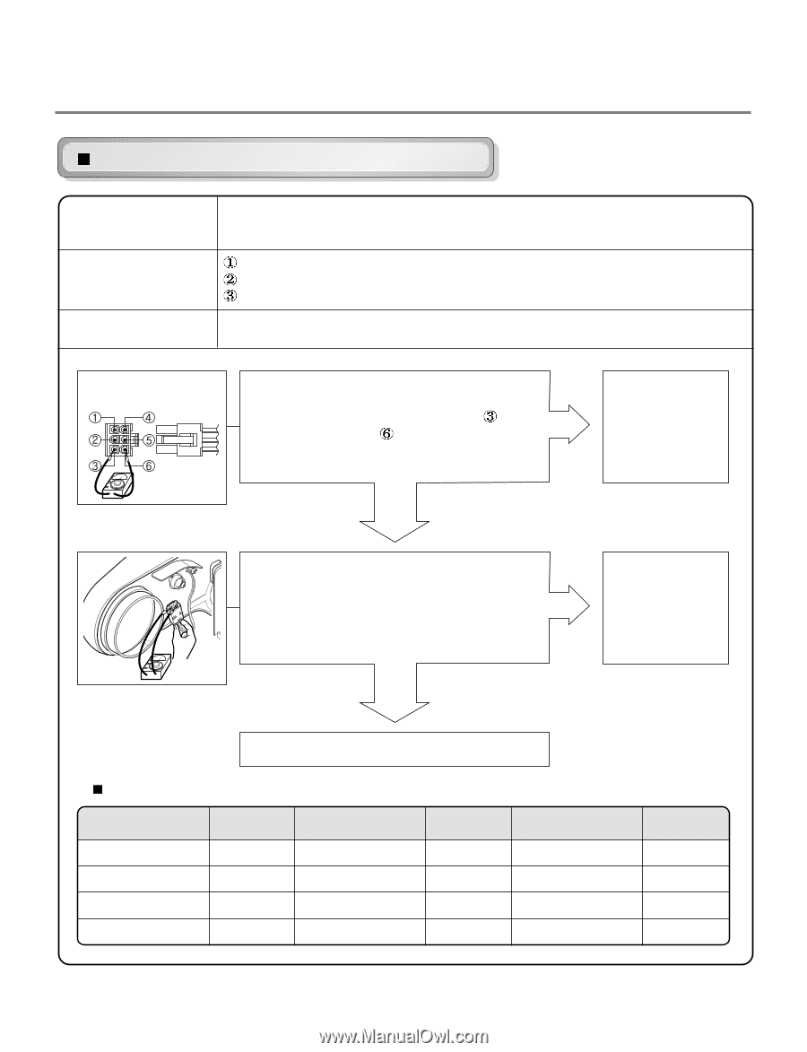
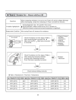
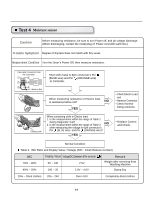
Test 2 Thermistor Test --- Measure with Power Off Caution Before measuring resistance, be sure to turn Power off, and do voltage discharge. (When discharging, contact the metal plug of Power cord with the Ground.) Trouble Symptom During Diagnostic Test, tE1 and tE2 Error occur. During operation, Heater would not turn off, or remains on. Difference between actual and sensed temperature is significant. Measurement Condition After turning Power off, measure the resistance. Take 6pin Connector from the Controller. Check if resistance is in the range of Table 1 when measuring 6pin connector Pin (Blue wire) and Pin (Red wire) connected to Controller. YES • Check if Control and 6Pin connector is properly connected. • Replace Controller. NO Check if resistance is in the range of Table 1 when measuring resistance between terminals after separating Harness NO From Thermistor assembly Connector. • Replace Thermistor. YES Check Harness-linking connector. Table 1. Resistance for Thermistor Temperature. Air TEMP.[°F (°C)] RES. [kΩ] Air TEMP.[°F (°C)] RES. [kΩ] Air TEMP.[°F (°C)] RES. [kΩ] 50°F (10°C) 18.0 90°F (32°C) 7.7 130°F (54°C) 2.9 60°F (16°C) 14.2 100°F (38°C) 6.2 140°F (60°C) 3.0 70°F (21°C) 11.7 110°F (43°C) 5.2 150°F (66°C) 2.5 80°F (27°C) 9.3 120°F (49°C) 4.3 160°F (71°C) 2.2 22
-
 1
1 -
2
-
3
-
4
-
5
-
6
-
7
-
8
-
9
-
10
-
11
-
12
-
13
-
14
-
15
-
16
-
 17
17 -
 18
18 -
 19
19 -
 20
20 -
 21
21 -
 22
22 -
 23
23 -
 24
24 -
 25
25 -
 26
26 -
 27
27 -
28
-
29
-
30
-
31
-
32
-
33
-
34
-
35
-
36
-
37
-
38
-
39
-
40
-
41
 |
 |