LG DLGX8388NM Owner's Manual - Page 12
Final Installation Check, Special Requirements For Manufactured Or Mobile Homes, Connecting Electric
 |
View all LG DLGX8388NM manuals
Add to My Manuals
Save this manual to your list of manuals |
Page 12 highlights
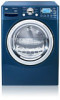
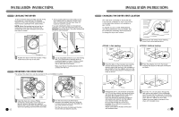
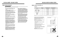
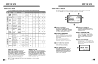
INSTALLATION INSTRUCTIONS CONNECTING ELECTRIC DRYERS (cont.) wWARNING: • Connect the power cord to the terminal block. Each colored wire should be connected to same color screw. Wire color indicated on manual is connected to the same color screw in block. Failure to follow these instructions may result in a short or overload. • Grounding through the neutral conductor is prohibited for: (1) new branch-circuit installations, (2) mobile homes, (3) recreational vehicles, and (4) areas where local codes prohibit grounding through the neutral conductor. Three-Wire Connection for Electric Dryers: Direct Wire • A 3-wire connection is NOT permitted on new construction after January 1, 1996. • A UL-listed strain relief is required. • Use UL-listed 3-wire #10 AWG-minimum copper conductor cable. • Allow at least 5 ft (1.5 m) length to allow for removal and reinstallation of the dryer. 1" (2.5 cm) Terminal Block UL-Listed Strain Relief 1 Remove 31⁄2 inches (8.9 cm) of the outer covering from the wire. Strip 1 inch (2.5 cm) insulation from each wire. Bend the ends of the three wires into a hook shape. UL-Listed 3-Wire Power Cord 2 Remove the terminal block access cover on the upper back of the dryer. Install a UL-listed strain relief into the power cord through-hole; then thread the power cable prepared in Step 1 through the strain relief. Hot Neutral Hot (Black) (White) (Red) Ground Screw Ground Wire 3 Attach the two hot leads of the power cord to the outer terminal block screws. Attach the neutral wire to the center terminal block screw. Connect the external ground (if required by local codes) to the green ground screw. Tighten all screws securely. Reinstall the terminal block access cover. 22 INSTALLATION INSTRUCTIONS SPECIAL REQUIREMENTS FOR MANUFACTURED OR MOBILE HOMES Any installation in a manufactured or mobile home must comply with the Manufactured Home Construction and Safety Standards Title 24 CFR, Part 32-80 or Standard CAN/CSA0Z240 MH and local codes and ordinances. If you are uncertain whether your proposed installation will comply with these standards, please contact a service and installation professional for assistance. • A gas dryer must be permanently attached to the floor. • The electrical connection for an electric dryer must be a 4-wire connection. More detailed information concerning the electrical connection is provided in the section Connecting Electric Dryers. • To reduce the risk of combustion and fire, the dryer must be vented to the outside. • DO NOT vent the dryer under a manufactured home or mobile home. • Electric dryers may be vented to the outside using the back, left, right, or bottom panel. • Gas dryers may be vented to the outside using the back, left, or bottom panel. Gas dryers may not be vented to the outside using the right side panel because of the burner housing. • The dryer exhaust duct must be affixed securely to the manufactured or mobile home structure, and the exhaust duct must be made of a material that will resist fire and combustion. It is recommended that you use a rigid or flexible metal duct. • DO NOT connect the dryer exhaust duct to any other duct, vent, chimney, or other exhaust duct. • Make sure the dryer has adequate access to outside fresh air to ensure proper operation. The opening for outside fresh air must be at least 25 in2 (163 cm2). • It is important that the clearance of the duct from any combustible construction be at least 2 in. (5 cm), and when venting the dryer to the outdoors, the dryer can be installed with a clearance of 1 in. (2.5 cm) at the sides and back of the dryer. • Please be aware that venting materials are not supplied with the dryer. You should obtain the venting materials necessary for proper installation. FINAL INSTALLATION CHECK Once you have completed the installation of the dryer and it is in its final location, confirm proper operation with the following tests. Testing Dryer Heating GAS MODELS Close the dryer door, press the ON/OFF switch to turn the dryer on, and start the dryer on a heat setting. When the dryer starts, the igniter should ignite the main burner. NOTE: If all air is not purged from the gas line, the gas igniter may turn off before the main burner ignites. If this happens, the igniter will reattempt gas ignition after approximately two minutes. ELECTRIC MODELS Close the dryer door, press the ON/OFF switch to turn the dryer on, and start the dryer on a heat setting. The exhaust air should be warm after the dryer has been operating for 3 minutes. Checking Airflow Effective dryer operation requires proper airflow. The adequacy of the airflow can be measured by evaluating the static pressure. Static pressure in the exhaust duct can be measured with a manometer, placed on the exhaust duct approximately 2 ft. (60.9 cm) from the dryer. Static pressure in the exhaust duct should not exceed 0.6 in. (1.5 cm). The dryer should be checked while the dryer is running with no load. Checking Levelness Once the dryer is in its final location, recheck the dryer to be sure it is level. Make sure it is level front to back and side to side, and that all 4 leveling feet are firmly on the floor. 23
-
 1
1 -
2
-
3
-
4
-
5
-
6
-
 7
7 -
 8
8 -
 9
9 -
 10
10 -
 11
11 -
 12
12 -
 13
13 -
 14
14 -
 15
15 -
 16
16 -
 17
17 -
18
-
19
-
20
-
21
-
22
-
23
-
24
-
25
-
26
-
27
-
28
-
29
-
30
-
31
-
32
-
33
-
34
-
35
-
36
-
37
-
38
-
39
-
40
-
41
-
42
-
43
-
44
-
45
 |
 |