LG HMC030KD1 Service Manual - Page 21
Installation
 |
View all LG HMC030KD1 manuals
Add to My Manuals
Save this manual to your list of manuals |
Page 21 highlights
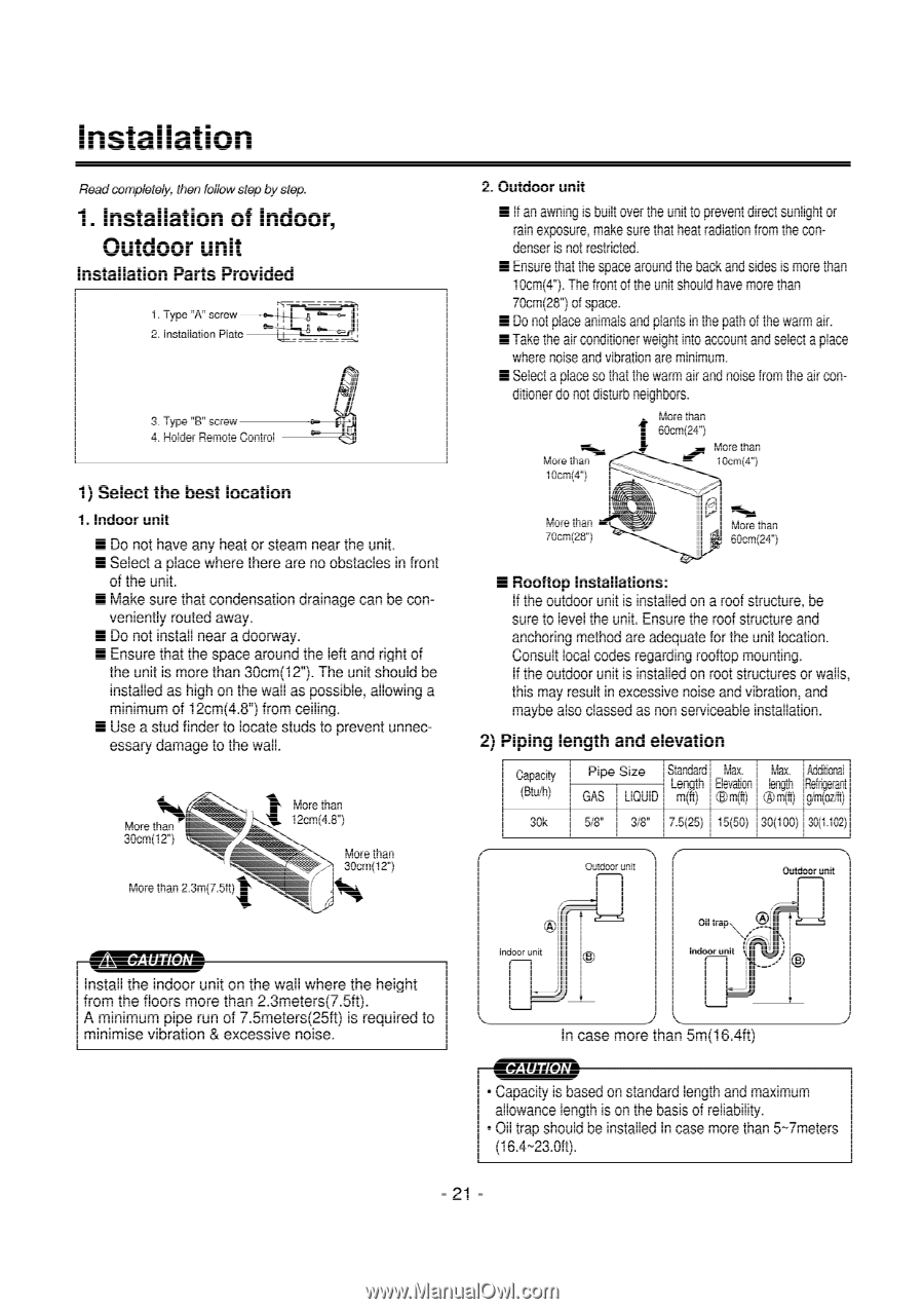
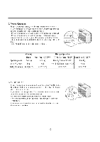
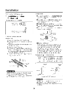
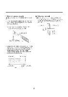
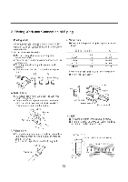
Installation Read completely. then follow step by step. 1. Installation of Indoor, Outdoor unit Installation Parts Provided 1. Type "A" screw -02. Installation Plate 3. Type 'B' screw 4. Holder Remote Control 1) Select the best location 1. Indoor unit • Do not have any heat or steam near the unit. • Select a place where there are no obstacles in front of the unit. • Make sure that condensation drainage can be con- veniently routed away. • Do not install near a doorway. • Ensure that the space around the left and right of the unit is more than 30cm(12"). The unit should be installed as high on the wall as possible, allowing a minimum of 12cnn(4.8") from ceiling. • Use a stud finder to locate studs to prevent unnecessary damage to the wall. More than 30cm(12") More than 2.3m(7.5ft) I More than 12cm(4.8") More than 30cm(12") ZL\ CAUTION Install the indoor unit on the wall where the height from the floors more than 2.3meters(7.5ft). A minimum pipe run of 7.5meters(25ft) is required to minimise vibration & excessive noise. 2. Outdoor unit • If an awning is built over the unit to prevent direct sunlight or rain exposure, make sure that heat radiation from the condenser is not restricted. • Ensure that the space around the back and sides is more than lOcnn(4"). The front of the unit should have more than 7Dcm(28") of space. • Do not place animals and plants in the path of the warm air. • Take the air conditioner weight into account and select a place where noise and vibration are minimum. • Select a place so that the warm air and noise from the air con- ditioner do not disturb neighbors. More than 10c m(4") More than 60cm(24") More than 10cm(4") More than 70cm(28. ) ohm More than 60cm(241 • Rooftop Installations: If the outdoor unit is installed an a roof structure, be sure to level the unit. Ensure the roof structure and anchoring method are adequate for the unit location. Consult local codes regarding rooftop mounting. If the outdoor unit is installed on root structures or walls, this may result in excessive noise and vibration, and maybe also classed as non serviceable installation. 2) Piping length and elevation Capacity (Btuiti) 30k Sandard Pipe Size l_ten F EleMvaaxtiOn leInlgIxil Refrigerant GAS LIQUID m(-t) C m(ft) lm(ft) girn(ort) 516. 3/8' 7.5(25) 15(50) 30(100) 30(1.102) Outdoor unit Outdoor unit Indoor unit Oil trap Indoor unit In case more than 5m(16.4ft) CAUTION • Capacity is based on standard length and maximum allowance length is on the basis of reliability. • Oil trap should be installed In case more than 5-7meters (16.4-23.0ft). -21 -
-
 1
1 -
2
-
3
-
4
-
5
-
6
-
7
-
8
-
9
-
10
-
11
-
12
-
13
-
14
-
15
-
 16
16 -
 17
17 -
 18
18 -
 19
19 -
 20
20 -
 21
21 -
 22
22 -
 23
23 -
 24
24 -
 25
25 -
 26
26 -
27
-
28
-
29
-
30
-
31
-
32
-
33
-
34
-
35
-
36
-
37
-
38
-
39
-
40
-
41
-
42
-
43
-
44
-
45
-
46
-
47
-
48
-
49
-
50
-
51
-
52
-
53
-
54
-
55
-
56
-
57
-
58
-
59
-
60
-
61
-
62
-
63
-
64
 |
 |