LG KE600 Service Manual - Page 51
USB charging circuit
 |
View all LG KE600 manuals
Add to My Manuals
Save this manual to your list of manuals |
Page 51 highlights
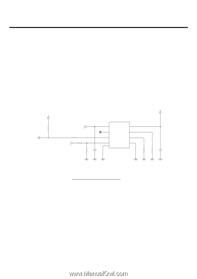
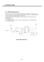
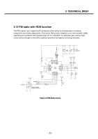
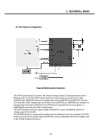
3. TECHNICAL BRIEF 3.14. USB charging circuit The USB charging circuit is a fully integrated USB VBUS voltage single-cell Li-ion battery charger circuit. The charger uses a CC/CV charge profile required by Li-ion batteries. CC charging current and End of charging current is programmable IREF & IMIN resistors. IREF resistor between this pin and the GND pin to set the charge current limit determined by the following equation: ICC = 12089/33K = 366mA The End Of Charging current is set by IMIN That can be programmed by the as following equation: IEOC = 11000/220K = 50mA USB_EOCn 2V72_IO R250 10K VBUS_USB R221 0 USB_CHG_ENn R216 0 U205 ISL6294 TP217 R251 C242 NA 1u 1 VIN 2 _PPR 3 _CHG 4 9 _EN PGND BAT 8 IREF 7 6 IMIN 5 GND VBAT C243 1u R218 220K R219 33K Figure 26 USB charging circuit - 52 -
-
 1
1 -
2
-
3
-
4
-
5
-
6
-
7
-
8
-
9
-
10
-
11
-
12
-
13
-
14
-
15
-
16
-
17
-
18
-
19
-
20
-
21
-
22
-
23
-
24
-
25
-
26
-
27
-
28
-
29
-
30
-
31
-
32
-
33
-
34
-
35
-
36
-
37
-
38
-
39
-
40
-
41
-
42
-
43
-
44
-
45
-
 46
46 -
 47
47 -
 48
48 -
 49
49 -
 50
50 -
 51
51 -
 52
52 -
 53
53 -
 54
54 -
 55
55 -
 56
56 -
57
-
58
-
59
-
60
-
61
-
62
-
63
-
64
-
65
-
66
-
67
-
68
-
69
-
70
-
71
-
72
-
73
-
74
-
75
-
76
-
77
-
78
-
79
-
80
-
81
-
82
-
83
-
84
-
85
-
86
-
87
-
88
-
89
-
90
-
91
-
92
-
93
-
94
-
95
-
96
-
97
-
98
-
99
-
100
-
101
-
102
-
103
-
104
-
105
-
106
-
107
-
108
-
109
-
110
-
111
-
112
-
113
-
114
-
115
-
116
-
117
-
118
-
119
-
120
-
121
-
122
-
123
-
124
-
125
-
126
-
127
-
128
-
129
-
130
-
131
-
132
-
133
-
134
-
135
-
136
-
137
-
138
-
139
-
140
-
141
-
142
-
143
-
144
-
145
-
146
-
147
-
148
-
149
-
150
-
151
-
152
-
153
-
154
-
155
-
156
-
157
-
158
-
159
-
160
-
161
-
162
-
163
-
164
-
165
-
166
-
167
-
168
 |
 |