LG LBC24360ST Service Manual - Page 13
Ptc-starter - model #
 |
View all LG LBC24360ST manuals
Add to My Manuals
Save this manual to your list of manuals |
Page 13 highlights
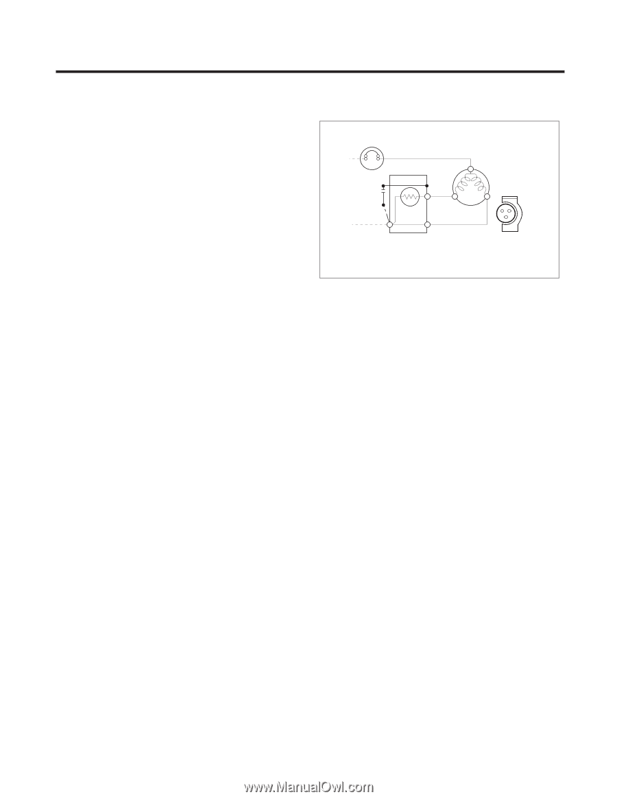
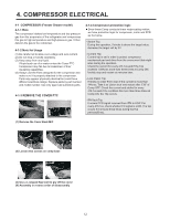
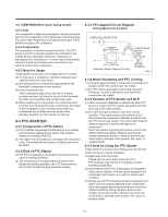
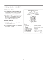
4-2 COMPRESSOR (Freezer Swing model) 4-2-1 Role The compressor intakes low temperature and low pressure gas from the evaporator of the refrigerator and compresses this gas to high-temperature and high-pressure gas. It then delivers the gas to the condenser. 4-2-2 Composition The compressor includes overload protection. The PTC starter and OLP (overload protector) are attached to the outside of the compressor. Since the compressor is manufactured to tolerances of 1 micron and is hermetically sealed in a dust and moisture-free environment, use extreme caution when repairing it. 4-2-3 Note for Usage (1) Be careful not to allow over-voltage and over-current. (2) If compressor is dropped or handled carelessly, poor operation and noise may result. (3) Use proper electric components appropriate to the Particular Compressor in your product. (4) Keep Compressor dry. If the Compressor gets wet (in the rain or a damp environment) and rust forms in the pin of the Hermetic Terminal, poor operation and contact may result. (5) When replacing the Compressor, be careful that dust, humidity, and soldering flux don't contaminate the inside of the compressor. Dust, humidity, and solder flux contaminate the cylinder and may cause noise, improper operation or even cause it to lock up. 4-3 PTC-STARTER 4-3-1 Composition of PTC-Starter (1) PTC (Positive Temperature Coefficient) is a no-contact semiconductor starting device which uses ceramic material consisting of BaTiO3. (2) The higher the temperature is, the higher the resistance value. These features are used as a starting device for the Motor. 4-3-2 Role of PTC-Starter (1) The PTC is attached to the Sealed Compressor and is used for starting the Motor. (2) The compressor is a single-phase induction motor. Durign the starting operation, the PTC allows current flow to both the start winding and main winding. 4-3-3 PTC-Applied Circuit Diagram Starting Method for the Motor OVERLOAD PROTECTOR L1 C 2 PTC 5 3 N S 6 PTC STARTER Resistance Starter Capacitor Running COMPRESSOR MOTOR M S M C SEALED TERMINAL Fig. 1 4-3-4 Motor Restarting and PTC Cooling (1) It requires approximately 5 minutes for the pressure to equalize before the compressor can restart. (2) The PTC device generates heat during operation. Therefore, it must be allowed to cool before the compressor can restart. 4-3-5 Relation of PTC-Starter and OLP (1) If the compressor attempts to restart before the PTC device is cooled, the PTC device will allow current to flow only to the main winding. (2) The OLP will open because of the over current condition. This same process will continue (3 to 5 times) when the compressor attempts to restart until the PTC device has cooled. The correct OLP must be properly attached to prevent damage to the compressor. Parts may appear physically identical but could have different electrical ratings. Replace parts by part number and model number. Using an incorrect part could result in damage to the product, fire, injury, or possibly death. 4-3-6 Note for Using the PTC-Starter (1) Be careful not to allow over-voltage and over-current. (2) Do not drop or handle carelessly. (3) Keep away from any liquid. If liquid such as oil or water enters the PTC, PTC materials may fail due to breakdown of their insulating capabilities. (4) If the exterior of the PTC is damaged, the resistance value may be altered. This can cause damage to the compressor and result in a no-start or hard-to-start condition. (5) Always use the PTC designed for the compressor and make sure it is properly attached to the compressor. Parts may appear physically identical but could have different electrical ratings. Replace parts by part number and model number. Using an incorrect part could result in damage to the product, fire, injury, or possibly death. 13
-
 1
1 -
2
-
3
-
4
-
5
-
6
-
7
-
 8
8 -
 9
9 -
 10
10 -
 11
11 -
 12
12 -
 13
13 -
 14
14 -
 15
15 -
 16
16 -
 17
17 -
 18
18 -
19
-
20
-
21
-
22
-
23
-
24
-
25
-
26
-
27
-
28
-
29
-
30
-
31
-
32
-
33
-
34
-
35
-
36
-
37
-
38
-
39
-
40
-
41
-
42
-
43
-
44
-
45
-
46
-
47
-
48
-
49
-
50
-
51
-
52
-
53
-
54
-
55
-
56
-
57
-
58
-
59
-
60
-
61
-
62
-
63
-
64
-
65
-
66
-
67
-
68
-
69
 |
 |