Lenovo A540 Lenovo A540/A740 Hardware Maintenance Manual - Page 47
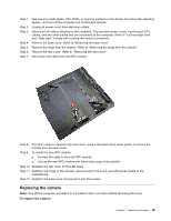
Remove the hinge from the chassis. Refer to Removing the hinge from the chassis.
 |
View all Lenovo A540 manuals
Add to My Manuals
Save this manual to your list of manuals |
Page 47 highlights
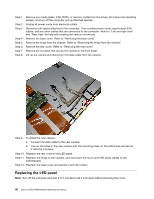
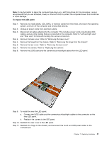
Note: It may be helpful to place the computer face-down on a soft flat surface for this procedure. Lenovo recommends that you use a blanket, towel, or other soft cloth to protect the computer screen from scratches or other damage. To replace the LED panel: Step 1. Step 2. Step 3. Step 4. Step 5. Step 6. Step 7. Step 8. Remove any media (disks, CDs, DVDs, or memory cards) from the drives, shut down the operating system, and turn off the computer and all attached devices. Unplug all power cords from electrical outlets. Disconnect all cables attached to the computer. This includes power cords, input/output (I/O) cables, and any other cables that are connected to the computer. Refer to "Left and right view" and "Rear view" for help with locating the various connectors. Remove the base cover. Refer to "Removing the base cover". Remove the hinge from the chassis. Refer to "Removing the hinge from the chassis". Remove the rear cover. Refer to "Removing the rear cover". Remove the camera. Refer to "Replacing the camera". Remove the LVDS cable and the camera-touch-backlight cables from the LED panel. Step 9. To install the new the LED panel: a. Connect the LVDS cable and the camera-touch-backlight cables to the connector on the new LED panel. b. Reattach the camera to the LED panel. Step 10. Reattach the rear cover to the LED panel. Step 11. Reattach the hinge to the chassis, and reconnect the touch and LED panel cables to the motherboard. Chapter 7. Replacing hardware 41
-
 1
1 -
2
-
3
-
4
-
5
-
6
-
7
-
8
-
9
-
10
-
11
-
12
-
13
-
14
-
15
-
16
-
17
-
18
-
19
-
20
-
21
-
22
-
23
-
24
-
25
-
26
-
27
-
28
-
29
-
30
-
31
-
32
-
33
-
34
-
35
-
36
-
37
-
38
-
39
-
40
-
41
-
 42
42 -
 43
43 -
 44
44 -
 45
45 -
 46
46 -
 47
47 -
 48
48 -
 49
49 -
 50
50 -
 51
51 -
 52
52 -
53
-
54
-
55
-
56
-
57
-
58
-
59
 |
 |
