Lenovo B750 IdeaCentre B750 Hardware Maintenance Manual
Lenovo B750 Manual
 |
View all Lenovo B750 manuals
Add to My Manuals
Save this manual to your list of manuals |
Lenovo B750 manual content summary:
- Lenovo B750 | IdeaCentre B750 Hardware Maintenance Manual - Page 1
IdeaCentre B750 Hardware Maintenance Manual ideaideaideaCentreidea Machine Types: 10144/F0AA - Lenovo B750 | IdeaCentre B750 Hardware Maintenance Manual - Page 2
- Lenovo B750 | IdeaCentre B750 Hardware Maintenance Manual - Page 3
IdeaCentre B750 Hardware Maintenance Manual Machine Types: 10144/F0AA - Lenovo B750 | IdeaCentre B750 Hardware Maintenance Manual - Page 4
First Edition (September 2013)3rd © Copyright Lenovo 2013. LIMITED AND RESTRICTED RIGHTS NOTICE: If data or software are delivered pursuant a General Services Administration "GSA" contract, use, reproduction, or disclosure is subject to restrictions set forth in Contract No. GS-35F-05925 - Lenovo B750 | IdeaCentre B750 Hardware Maintenance Manual - Page 5
20 Undetermined problems 20 Chapter 7. Locating connectors, controls and components 21 Chapter 8. Replacing hardware . . . . 27 General information 27 Replacing the keyboard and mouse 28 Replacing the power cord or power adapter . . . 28 Removing the computer cover 29 Replacing a memory module - Lenovo B750 | IdeaCentre B750 Hardware Maintenance Manual - Page 6
iv IdeaCentre B750Hardware Maintenance Manual - Lenovo B750 | IdeaCentre B750 Hardware Maintenance Manual - Page 7
manual This manual contains service and reference information for IdeaCentre B750 computers listed on the cover. It is intended only for trained servicers who are familiar with Lenovo computer products. Before servicing a Lenovo document avant d'exécuter les instructions. Lesen Sie unbedingt alle - Lenovo B750 | IdeaCentre B750 Hardware Maintenance Manual - Page 8
2 IdeaCentre B750Hardware Maintenance Manual - Lenovo B750 | IdeaCentre B750 Hardware Maintenance Manual - Page 9
safe place, away from all personnel, while you are servicing the machine. • Keep your tool case away from with a nonconductive clip, approximately 8 centimeters (3 inches) from the end. • Do not wear instructed otherwise in the installation and configuration procedures. © Copyright Lenovo 2013 3 - Lenovo B750 | IdeaCentre B750 Hardware Maintenance Manual - Page 10
-off the wall box that supplies power to the machine and to lock the wall box in the off the power, if necessary. - Use only one hand when working with powered-on electrical equipment; high voltages; these instructions are in the touching can cause personal injury and machine damage. • Do not service - Lenovo B750 | IdeaCentre B750 Hardware Maintenance Manual - Page 11
had required safety items installed to protect users and service personnel from injury. This guide addresses only those items. However, good judgment should be could be and whether you can continue without first correcting the problem. Consider these conditions and the safety hazards they present: • - Lenovo B750 | IdeaCentre B750 Hardware Maintenance Manual - Page 12
on your body. • Prevent the part from touching your clothing. Most clothing is insulative and retains provide protection that meets the specific service requirement. Note: The use of product. • When possible, use one hand only to connect or disconnect signal covers, unless instructed otherwise in the - Lenovo B750 | IdeaCentre B750 Hardware Maintenance Manual - Page 13
: • Do not remove the covers. Removing the covers of the laser product could result in exposure to hazardous laser radiation. There are no serviceable parts inside the device. • Use of controls or adjustments or performance of procedures other than those specified herein might result in hazardous - Lenovo B750 | IdeaCentre B750 Hardware Maintenance Manual - Page 14
the power switch on the power supply do not turn off the electrical current supplied to the device. The device also might have more than one power cord. To remove all electrical current from the device, ensure that all power cords are disconnected from the power source. 2 1 CAUTION: Do not place - Lenovo B750 | IdeaCentre B750 Hardware Maintenance Manual - Page 15
that applies to all machine types supported by this publication. Specifications This section lists the physical specifications for your computer. Type IdeaCentre B750 This section lists the physical specifications. Environment Air temperature: frequency: 47Hz-63Hz © Copyright Lenovo 2013 9 - Lenovo B750 | IdeaCentre B750 Hardware Maintenance Manual - Page 16
10 IdeaCentre B750Hardware Maintenance Manual - Lenovo B750 | IdeaCentre B750 Hardware Maintenance Manual - Page 17
servicing might have been rearranged or the drive startup sequence changed. Be extremely careful during write operations such as copying, saving, or formatting. Data or programs can be overwritten if you select an incorrect drive. General error messages appear if a problem instructions instructions: - Lenovo B750 | IdeaCentre B750 Hardware Maintenance Manual - Page 18
12 IdeaCentre B750Hardware Maintenance Manual - Lenovo B750 | IdeaCentre B750 Hardware Maintenance Manual - Page 19
Setup Utility menu. The keys used to perform various tasks are displayed on the bottom of each screen. Using passwords You can use the Lenovo BIOS Setup Utility program to set passwords to prevent unauthorized persons from gaining access to your computer and data. See "Starting the Setup Utility - Lenovo B750 | IdeaCentre B750 Hardware Maintenance Manual - Page 20
access the Lenovo BIOS Setup Utility Lenovo BIOS Setup Utility program (see "Starting the Lenovo BIOS Lenovo BIOS Setup Utility program (see "Starting the Lenovo BIOS 4. Return to the Lenovo BIOS Setup Utility program menu is set, you cannot start the Lenovo BIOS Setup Utility program until a valid - Lenovo B750 | IdeaCentre B750 Hardware Maintenance Manual - Page 21
-On Password, do the following: 1. Start the Lenovo BIOS Setup Utility program (See "Starting the Lenovo BIOS Setup Utility program" on page 13.) 2. From the can be used. ATA Drive Setup Select IDE or ACHI mode. Device driver support is required for ACHI mode. Depending on how the hard disk image - Lenovo B750 | IdeaCentre B750 Hardware Maintenance Manual - Page 22
Onboard Ethernet Support or Boot Agent. 4. Select Disabled or Enabled and press the Enter key. 5. Return to the Lenovo BIOS Setup Utility such as the CD/DVD-ROM drive disk or hard disk as expected, follow one of the procedures below. Selecting a temporary startup device Use this procedure to - Lenovo B750 | IdeaCentre B750 Hardware Maintenance Manual - Page 23
Utility program After you finish viewing or changing settings, press the Esc key to return to the Lenovo BIOS Setup Utility program main menu. You might have to press the Esc key several times. Do one of the following: • If you want to save the new settings, select Save changes and Exit from - Lenovo B750 | IdeaCentre B750 Hardware Maintenance Manual - Page 24
18 IdeaCentre B750Hardware Maintenance Manual - Lenovo B750 | IdeaCentre B750 Hardware Maintenance Manual - Page 25
used to help you decide which FRUs to have available when servicing a computer. If you are unable to correct the problem using this index, go to "Undetermined problems" on page 20. Notes: • If you have both an . FRU/Action Reseat connectors Power Cord Power-on Switch © Copyright Lenovo 2013 19 - Lenovo B750 | IdeaCentre B750 Hardware Maintenance Manual - Page 26
BIOS then ignores the missing keyboard during POST. The BIOS problems 1. Power-off the computer. 2. Remove or disconnect the following components (if connected or installed) one at a time. a. External devices (modem, printer, or mouse) b. Extended video memory c. External Cache d. External Cache RAM - Lenovo B750 | IdeaCentre B750 Hardware Maintenance Manual - Page 27
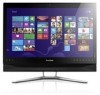
drive indicator 6. Bluetooth status indicator 7. Wi-Fi status indicator 8. Volume down 9. Volume up 10. Brightness down 11. Brightness up 12. Novo Vision switch 13. PC mode/HDMI-in switch 14. Monitor ON/OFF Attention: The effective range of the Built-in IR Emitter is 10 feet (3m). © Copyright - Lenovo B750 | IdeaCentre B750 Hardware Maintenance Manual - Page 28
of connectors, controls and components on the left and right side of the computer. 6 1 2 3 4 5 7 1. USB 3.0 connecto 2. Headphone connector 3. Microphone connector 4. USB 3.0 connector 5. Memory card reader 6. Optical drive eject button 7. Power button 22 IdeaCentre B750Hardware Maintenance - Lenovo B750 | IdeaCentre B750 Hardware Maintenance Manual - Page 29
Rear view The following illustration shows the location of connectors and components on the rear of the computer. 8 1. TV tuner connector (selected models only) 2. Ethernet connector 3. HDMI-in connector 4. HDMI-out connector 3 7 1 2456 5. USB 3.0 connectors (2) 6. USB 2.0 connectors (2) 7. - Lenovo B750 | IdeaCentre B750 Hardware Maintenance Manual - Page 30
. Speaker system 16. Power switch board 17. Wi-Fi card 18. TV-Tuner card 19. Hard disk drive 20. Power supply 24 IdeaCentre B750Hardware Maintenance Manual - Lenovo B750 | IdeaCentre B750 Hardware Maintenance Manual - Page 31
The motherboard (sometimes called the planar or system board) is the main circuit board in your computer. It provides basic computing functions and supports a variety of devices that are factory-installed or that you can install later. The following illustration shows the location of connectors and - Lenovo B750 | IdeaCentre B750 Hardware Maintenance Manual - Page 32
26 IdeaCentre B750Hardware Maintenance Manual - Lenovo B750 | IdeaCentre B750 Hardware Maintenance Manual - Page 33
with your computer. To obtain copies of the Safety and Warranty Guide, go to the Support Web site at: http://consumersupport.lenovo.com. Note: Use only parts provided by Lenovo. General information Pre-disassembly instructions Before proceeding with the disassembly procedure, make sure that you do - Lenovo B750 | IdeaCentre B750 Hardware Maintenance Manual - Page 34
3. Remove any media (disks, CDs, DVDs or memory cards) from the drives, shut down the operating keyboard will be connected to a USB connector on one side or at the rear of the computer. power cord and power adapter: Step 1. Remove any media (diskettes, CDs, DVDs, or memory cards) from the drives - Lenovo B750 | IdeaCentre B750 Hardware Maintenance Manual - Page 35
power cord and adapter from the computer. Lenovo recommends that you use a blanket, towel, or other soft cloth to protect the computer screen from scratches or other damage. To remove the computer cover: Step 1. Step 2. Step 3. Step 4. Remove any media (disks, CDs, DVDs, or memory hardware 29 - Lenovo B750 | IdeaCentre B750 Hardware Maintenance Manual - Page 36
the computer face-down on a soft flat surface for this procedure. Lenovo recommends that you use a blanket, towel, or other soft cloth to protect the computer screen from scratches or other damage. To replace a memory module Step 1. Step 2. Step 3. Step 4. Step 5. Remove any media (disks, CDs - Lenovo B750 | IdeaCentre B750 Hardware Maintenance Manual - Page 37
Step 3. Step 4. Step 5. Disconnect all cables attached to the computer. This includes power cords, input/output (I/O) cables, and any other cables that are connected to the computer. Refer to "Left and right view" and "Rear view" for help with locating the various connectors. Remove the rear cover. - Lenovo B750 | IdeaCentre B750 Hardware Maintenance Manual - Page 38
drive Step 1. Step 2. Step 3. Step 4. Step 5. Remove any media (disks, CDs, DVDs, or memory cards) from the drives, shut down the operating system, and turn off the computer and all attached devices. secure the optical drive to the metal bracket. 1 32 IdeaCentre B750Hardware Maintenance Manual - Lenovo B750 | IdeaCentre B750 Hardware Maintenance Manual - Page 39
face-down on a soft flat surface. Lenovo recommends that you use a blanket, towel, or other soft cloth to protect the screen surface from scratches or other damage. To remove the computer stand: Step 1. Step 2. Step 3. Remove any media (disks, CDs, DVDs or memory cards) from the drives, shut down - Lenovo B750 | IdeaCentre B750 Hardware Maintenance Manual - Page 40
stand with the mounting holes in the Lenovo recommends that you use a blanket, towel, or other soft cloth to protect the computer screen from scratches or other damage. To remove the middle cover Step 1. Step 2. Step 3. Step 4. Step 5. Step 6. Remove any media (disks, CDs, DVDs, or memory Manual - Lenovo B750 | IdeaCentre B750 Hardware Maintenance Manual - Page 41
for this procedure. Lenovo recommends that you use a blanket, towel, or other soft cloth to protect the computer screen from scratches or other damage. To replace the converter board: Step 1. Step 2. Step 3. Step 4. Step 5. Step 6. Step 7. Remove any media (disks, CDs, DVDs, or memory cards) from - Lenovo B750 | IdeaCentre B750 Hardware Maintenance Manual - Page 42
with the mounting holes and pins Lenovo recommends that you use a blanket, towel, or other soft cloth to protect the computer screen from scratches or other damage. To replace the camera: Step 1. Step 2. Step 3. Step 4. Step 5. Step 6. Step 7. Remove any media (disks, CDs, DVDs, or memory Manual - Lenovo B750 | IdeaCentre B750 Hardware Maintenance Manual - Page 43
Step 8. Push the two pin to release the camera 1 , then lift the camera out. 2 Step 9. Disconnect the data cable from the camera. 3 Step 10. Push the pins to release the camera out of housing 4 , then lift the camera out. 5 Step 11. To install the new camera: a. Line up the new camera with the - Lenovo B750 | IdeaCentre B750 Hardware Maintenance Manual - Page 44
-down on a soft flat surface for this procedure. Lenovo recommends that you use a blanket, towel, or other soft cloth to protect the computer screen from scratches or other damage. To replace the EMI cover Step 1. Remove any media (disks, CDs, DVDs, or memory cards) from the drives, shut down the - Lenovo B750 | IdeaCentre B750 Hardware Maintenance Manual - Page 45
10. To reinstall the EMI cover: a. Line up the EMI cover with the mounting holes on the chassis and secure it with the five screws. Step 11. Step 6. Step 7. Step 8. Remove any media (disks, CDs, DVDs, or memory cards) from the drives, shut down the operating system, and turn off the computer - Lenovo B750 | IdeaCentre B750 Hardware Maintenance Manual - Page 46
11. To install the new subwoofer: a. Line up the new subwoofer with mounting screws on the chassis, the place the new subwoofer into position. b. Connect the speaker system: Step 1. Remove any media (disks, CDs, DVDs, or memory cards) from the drives, shut down the operating system, and turn off the - Lenovo B750 | IdeaCentre B750 Hardware Maintenance Manual - Page 47
1 Step 10. Lift up the speaker system to remove it. 2 Step 11. To install the new speaker system: a. Line up the new speaker system with mounting screws on the chassis, the place the new speaker into position. b. Connect the new speaker cable to motherboard. Step 12. Reattach the EMI cover, middle - Lenovo B750 | IdeaCentre B750 Hardware Maintenance Manual - Page 48
Lenovo recommends that you use a blanket, towel, or other soft cloth to protect the computer screen from scratches or other damage. To remove the power supply: Step 1. Step 2. Step 3. Step 4. Step 5. Step 6. Step 7. Step 8. Step 9. Remove any media (disks, CDs, or memory Maintenance Manual - Lenovo B750 | IdeaCentre B750 Hardware Maintenance Manual - Page 49
the cover. To replace the TV tuner card Step 1. Step 2. Step 3. Step 4. Step 5. Step 6. Step 7. Step 8. Remove any media (disks, CDs, DVDs, or memory cards) from the drives, shut down the operating system, and turn off the computer and all attached devices. Unplug all power cords from electrical - Lenovo B750 | IdeaCentre B750 Hardware Maintenance Manual - Page 50
2. Step 3. Step 4. Step 5. Step 6. Step 7. Step 8. Remove any media (disks, CDs, DVDs, or memory cards) from the drives, shut down the operating system, and turn off the computer and all attached devices. Unplug all . Refer to "Removing the EMI cover". 44 IdeaCentre B750Hardware Maintenance Manual - Lenovo B750 | IdeaCentre B750 Hardware Maintenance Manual - Page 51
for this procedure. Lenovo recommends that you use a blanket, towel, or other soft cloth to protect the computer screen from scratches or other damage. To replace the system fan Step 1. Step 2. Step 3. Step 4. Step 5. Step 6. Step 7. Step 8. Remove any media (disks, CDs, DVDs or memory cards) from - Lenovo B750 | IdeaCentre B750 Hardware Maintenance Manual - Page 52
Lenovo recommends that you use a blanket, towel, or other soft cloth to protect the computer screen from scratches or other damage. To replace the heat-sink: Step 1. Step 2. Step 3. Step 4. Step 5. Step 6. Step 7. Step 8. Step 9. Remove any media (disks, CDs, DVDs or memory Maintenance Manual - Lenovo B750 | IdeaCentre B750 Hardware Maintenance Manual - Page 53
sink: a. Line up the new heat-sink with mounting holes on motherboard and secure it with the eight screws Step 1. Remove any media (disks, CDs, DVDs, or memory cards) from the drives, shut down the operating system, touch the gold contacts on the bottom of the microprocessor. When handing - Lenovo B750 | IdeaCentre B750 Hardware Maintenance Manual - Page 54
Step 12. Lift the microprocessor straight up and out of the socket. 3 Attention: Do not touch the gold contacts on the bottom of the microprocessor. When handing the microprocessor, touch only the sides. Note: Do not drop anything onto the microprocessor socket while it is exposed. The socket pins - Lenovo B750 | IdeaCentre B750 Hardware Maintenance Manual - Page 55
and wait 3 to 5 minutes to let it cool down before removing the cover. To replace the motherboard: Step 1. Remove any media (disks, CDs, DVDs, or memory cards) from the drives, shut down the operating system, and turn off the computer and all attached devices. Step 2. Unplug all power cords from - Lenovo B750 | IdeaCentre B750 Hardware Maintenance Manual - Page 56
new motherboard and secure the CPU in the socket, close the CPU retainer and lock it into position with the small handle. e. Install the memory module(s) to the new motherboard. f. Install the heat-sink to the new motherboard. g. Install the system fans to the new motherboard. h. Connect the antenna - Lenovo B750 | IdeaCentre B750 Hardware Maintenance Manual - Page 57
on a soft flat surface for this procedure. Lenovo recommends that you use a blanket, towel, or other soft cloth to protect the computer screen from scratches or other damage. To replace the LED panel module: Step 1. Remove any media (disks, CDs, DVDs, or memory cards) from the drives, shut down the - Lenovo B750 | IdeaCentre B750 Hardware Maintenance Manual - Page 58
b. Optical disk drive power and SATA connector and cables. 52 IdeaCentre B750Hardware Maintenance Manual - Lenovo B750 | IdeaCentre B750 Hardware Maintenance Manual - Page 59
c. Wi-Fi antenna cables. Chapter 8. Replacing hardware 53 - Lenovo B750 | IdeaCentre B750 Hardware Maintenance Manual - Page 60
, to the motherboard and chassis. Step 19. Reattach the EMI cover, middle cover, optical drive, computer stand and the rear cover. 54 IdeaCentre B750Hardware Maintenance Manual - Lenovo B750 | IdeaCentre B750 Hardware Maintenance Manual - Page 61
supported by this publication. Additional Service Information This chapter provides additional information that the service Power Management (APM) BIOS mode is ignored. Not all operating systems support ACPI BIOS mode. Automatic Power- LAN adapter card to wake the System. © Copyright Lenovo 2013 55
-
 1
1 -
 2
2 -
 3
3 -
 4
4 -
 5
5 -
 6
6 -
 7
7 -
8
-
9
-
10
-
11
-
12
-
13
-
14
-
15
-
16
-
17
-
18
-
19
-
20
-
21
-
22
-
23
-
24
-
25
-
26
-
27
-
28
-
29
-
30
-
31
-
32
-
33
-
34
-
35
-
36
-
37
-
38
-
39
-
40
-
41
-
42
-
43
-
44
-
45
-
46
-
47
-
48
-
49
-
50
-
51
-
52
-
53
-
54
-
55
-
56
-
57
-
58
-
59
-
60
-
61
 |
 |

IdeaCentre B750
Hardware Maintenance Manual
Machine Types: 10144/F0AA