Lenovo C325 Lenovo C225\C320\C325 Hardware Replacement Guide V1.0 - Page 17
Replacing the optical drive, To remove the optical drive
 |
View all Lenovo C325 manuals
Add to My Manuals
Save this manual to your list of manuals |
Page 17 highlights
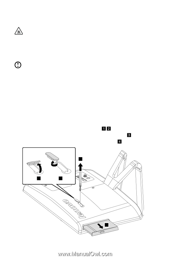
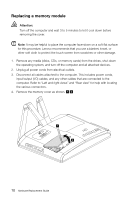
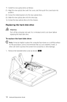
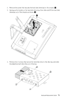
Replacing the optical drive Attention: Turn off the computer and wait 3 to 5 minutes to let it cool down before replacing the optical drive. To remove the optical drive: Note: It may be helpful to place the computer face-down on a soft flat surface for this procedure. Lenovo recommends that you use a blanket, towel, or other soft cloth to protect the screen from scratches or other damage. 1. Remove any media (disks, CDs, or memory cards) from the drives, shut down the operating system, and turn off the computer and all attached devices. 2. Unplug all power cords from electrical outlets. 3. Disconnect all cables attached to the computer. This includes power cords, input/output (I/O) cables, and any other cables that are connected to the computer. Refer to "Left and right views" and "Rear view" for help with locating the various connectors. 4. Remove the rubber cap that protects the screw. 5. Remove the screw that secures the optical drive to the chassis. 6. Push the optical drive so that it slides out of the drive bay. 3 1 2 4 12 Hardware Replacement Guide
-
 1
1 -
2
-
3
-
4
-
5
-
6
-
7
-
8
-
9
-
10
-
11
-
 12
12 -
 13
13 -
 14
14 -
 15
15 -
 16
16 -
 17
17 -
 18
18 -
 19
19 -
 20
20 -
 21
21 -
 22
22 -
23
-
24
-
25
 |
 |