Lenovo C40-05 Lenovo C40 Series All-In-One Computer Hardware Maintenance Manua - Page 35
Step 6. Remove the stand holder. Refer to Removing the stand holder.
 |
View all Lenovo C40-05 manuals
Add to My Manuals
Save this manual to your list of manuals |
Page 35 highlights
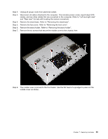
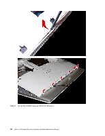
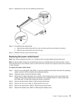
Step 2. Step 3. Step 4. Step 5. Step 6. Step 7. Unplug all power cords from electrical outlets. Disconnect all cables attached to the computer. This includes power cords, input/output (I/O) cables, and any other cables that are connected to the computer. Refer to "Left and right view" and "Rear view" for help with locating the various connectors. Remove the stand base. Refer to "Removing the stand base". Remove the foot cover. Refer to "Removing the foot cover". Remove the stand holder. Refer to "Removing the stand holder". Remove the six screws that secure the middle cover to the chassis, then Step 8. The middle cover is pinned to the front bezel. Use the flat head of a spudger to pries out the middle cover as shown. Chapter 7. Replacing hardware 29
-
 1
1 -
2
-
3
-
4
-
5
-
6
-
7
-
8
-
9
-
10
-
11
-
12
-
13
-
14
-
15
-
16
-
17
-
18
-
19
-
20
-
21
-
22
-
23
-
24
-
25
-
26
-
27
-
28
-
29
-
 30
30 -
 31
31 -
 32
32 -
 33
33 -
 34
34 -
 35
35 -
 36
36 -
 37
37 -
 38
38 -
 39
39 -
 40
40 -
41
-
42
-
43
-
44
-
45
-
46
-
47
-
48
-
49
-
50
-
51
-
52
-
53
-
54
-
55
-
56
-
57
-
58
-
59
-
60
-
61
-
62
-
63
-
64
-
65
-
66
-
67
-
68
-
69
-
70
-
71
-
72
-
73
-
74
-
75
 |
 |
