Lenovo C40-05 Lenovo C40 Series All-In-One Computer Hardware Maintenance Manua - Page 40
Replacing the converter board, cables
 |
View all Lenovo C40-05 manuals
Add to My Manuals
Save this manual to your list of manuals |
Page 40 highlights
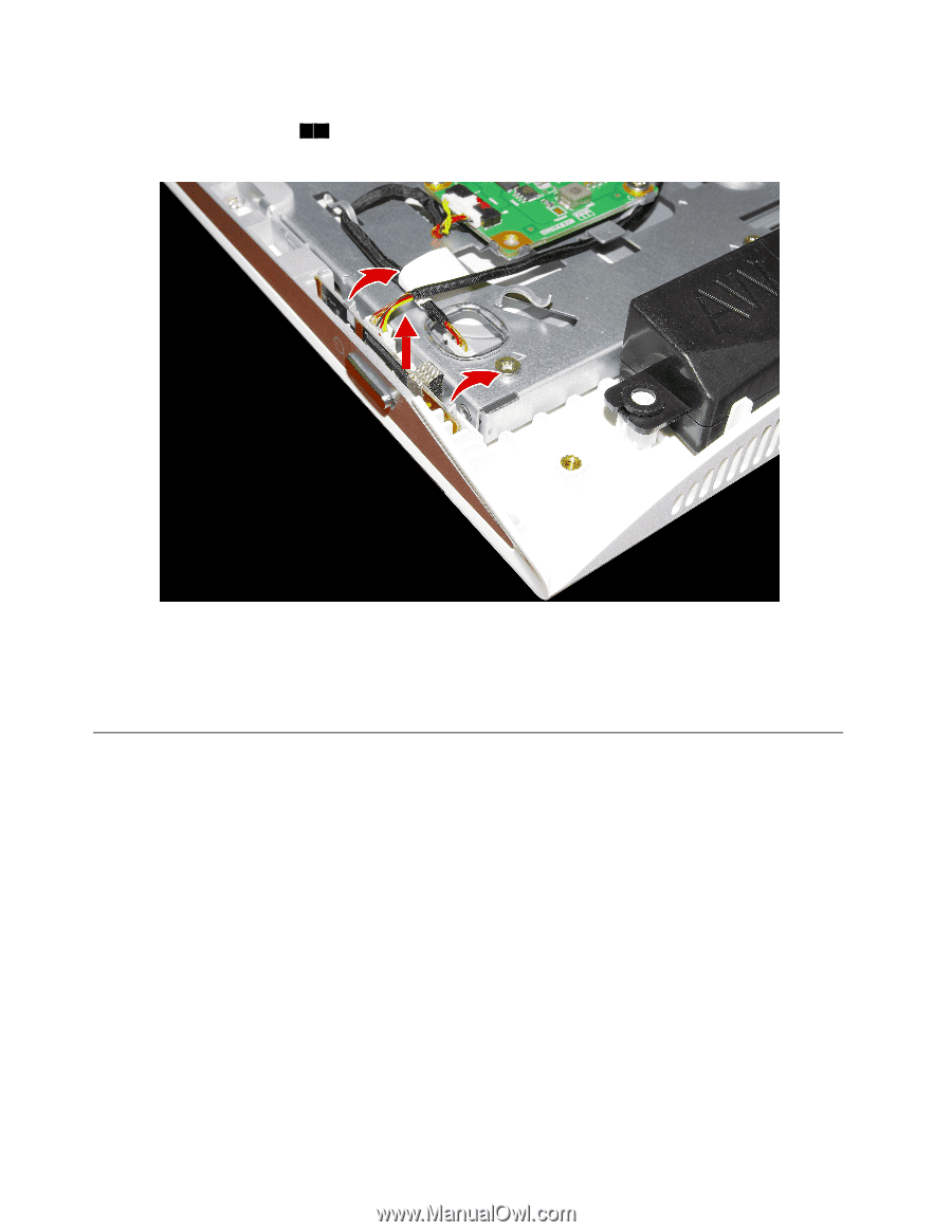
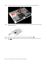
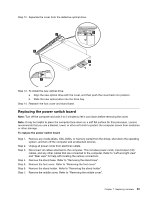
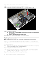
Step 8. Push the locking pin outward to release the power switch board, then lift up the power switch board to remove it. 1 2 Step 9. Disconnect the data cable from the power switch board. Step 10. To install the power switch board: a. Line up the notches on the new power switch board with the keys in the slot. b. Secure the power switch board with the locking pin. Step 11. Reattach the middle cover, stand holder, foot cover and stand base. Replacing the converter board Note: Turn off the computer and wait 3 to 5 minutes to let it cool down before removing the cover. Note: It may be helpful to place the computer face-down on a soft flat surface for this procedure. Lenovo recommends that you use a blanket, towel, or other soft cloth to protect the computer screen from scratches or other damage. To replace the converter board: Step 1. Step 2. Step 3. Step 4. Step 5. Step 6. Step 7. Remove any media (disks, CDs, DVDs, or memory cards) from the drives, shut down the operating system, and turn off the computer and all attached devices. Unplug all power cords from electrical outlets. Disconnect all cables attached to the computer. This includes power cords, input/output (I/O) cables, and any other cables that are connected to the computer. Refer to "Left and right view" and "Rear view" for help with locating the various connectors. Remove the stand base. Refer to "Removing the stand base". Remove the foot cover. Refer to "Removing the foot cover". Remove the stand holder. Refer to "Removing the stand holder". Remove the middle cover. Refer to "Removing the middle cover". 34 Lenovo C40 Series All-In-One Computer Hardware Maintenance Manual
-
 1
1 -
2
-
3
-
4
-
5
-
6
-
7
-
8
-
9
-
10
-
11
-
12
-
13
-
14
-
15
-
16
-
17
-
18
-
19
-
20
-
21
-
22
-
23
-
24
-
25
-
26
-
27
-
28
-
29
-
30
-
31
-
32
-
33
-
34
-
 35
35 -
 36
36 -
 37
37 -
 38
38 -
 39
39 -
 40
40 -
 41
41 -
 42
42 -
 43
43 -
 44
44 -
 45
45 -
46
-
47
-
48
-
49
-
50
-
51
-
52
-
53
-
54
-
55
-
56
-
57
-
58
-
59
-
60
-
61
-
62
-
63
-
64
-
65
-
66
-
67
-
68
-
69
-
70
-
71
-
72
-
73
-
74
-
75
 |
 |