Lenovo H100 Lenovo 3000 H Series Hardware Maintenance Manual - Page 46
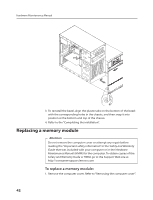
For this procedure, it helps to lay the computer on its side.
 |
View all Lenovo H100 manuals
Add to My Manuals
Save this manual to your list of manuals |
Page 46 highlights
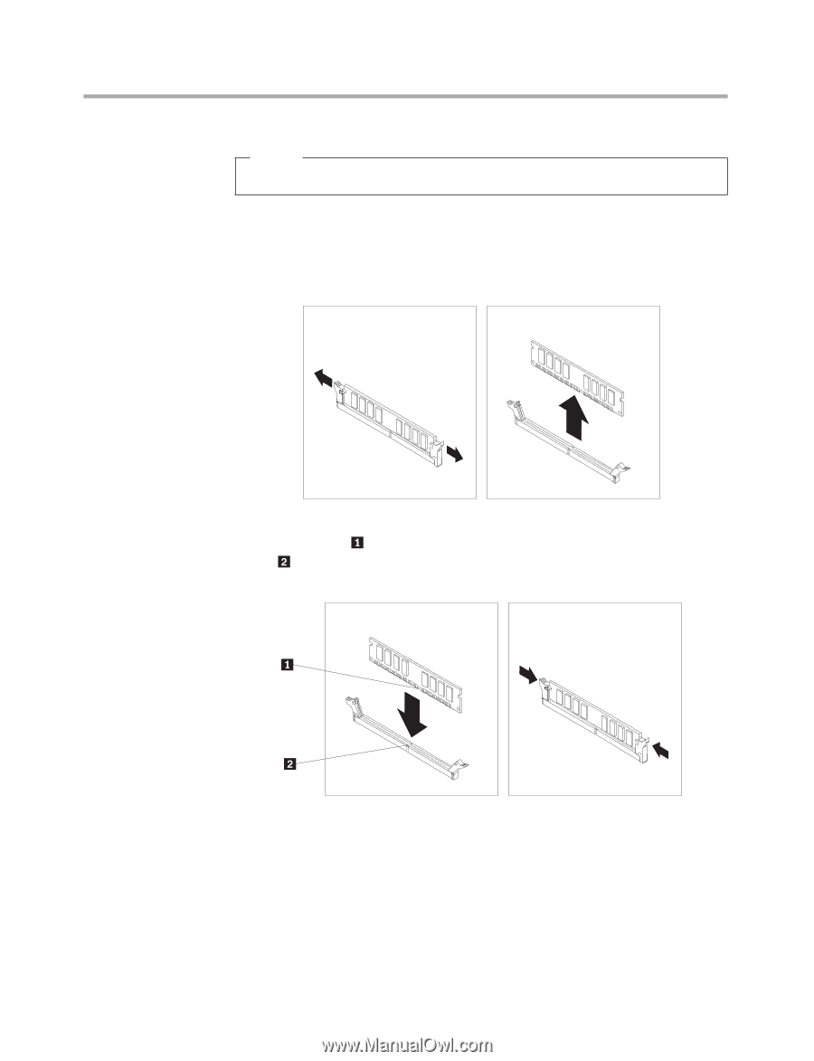
Chapter 7. Replacing hardware Note: For this procedure, it helps to lay the computer on its side. 2. Locate the memory module connectors. Refer to "Locating components". 3. Remove the memory module being replaced by opening the retaining clips as shown. 4. Position the new memory module over the memory connector. Make sure the notch on the memory aligns correctly with the connector key on the system board. Push the memory module straight down into the connector until the retaining clips close. 5. Refer to the "Completing the installation". 43
-
 1
1 -
2
-
3
-
4
-
5
-
6
-
7
-
8
-
9
-
10
-
11
-
12
-
13
-
14
-
15
-
16
-
17
-
18
-
19
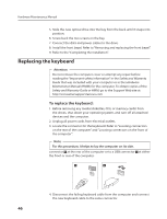
-
20
-
21
-
22
-
23
-
24
-
25
-
26
-
27
-
28
-
29
-
30
-
31
-
32
-
33
-
34
-
35
-
36
-
37
-
38
-
39
-
40
-
 41
41 -
 42
42 -
 43
43 -
 44
44 -
 45
45 -
 46
46 -
 47
47 -
 48
48 -
 49
49 -
 50
50 -
 51
51 -
52
-
53
-
54
-
55
-
56
-
57
-
58
 |
 |
Chapter 7. Replacing hardware
43
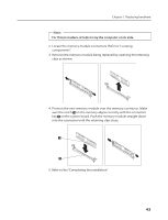
Note:
For this procedure, it helps to lay the computer on its side.
2. Locate the memory module connectors. Refer to “Locating
components”.
3. Remove the memory module being replaced by opening the retaining
clips as shown.
4. Position the new memory module over the memory connector. Make
sure the notch
on the memory aligns correctly with the connector
key
on the system board. Push the memory module straight down
into the connector until the retaining clips close.
5. Refer to the “Completing the installation”.