Lenovo H50-55 Lenovo H50 Series Hardware Maintenance Manual - Page 58
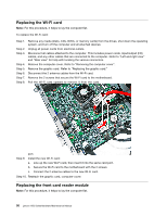
Step 10. Remove the Wi-Fi card. Refer to Replacing the Wi-Fi card.
 |
View all Lenovo H50-55 manuals
Add to My Manuals
Save this manual to your list of manuals |
Page 58 highlights
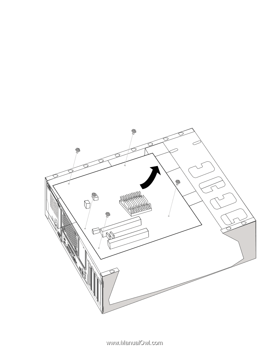
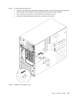
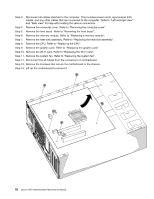
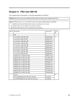
Step 3. Disconnect all cables attached to the computer. This includes power cords, input/output (I/O) cables, and any other cables that are connected to the computer. Refer to "Left and right view" and "Rear view" for help with locating the various connectors. Step 4. Remove the computer cover. Refer to "Removing the computer cover". Step 5. Remove the front bezel. Refer to "Removing the front bezel". Step 6. Remove the memory module. Refer to "Replacing a memory module". Step 7. Remove the heat-sink assembly. Refer to "Replacing the heat-sink assembly". Step 8. Remove the CPU. Refer to "Replacing the CPU". Step 9. Remove the graphic card. Refer to "Replacing the graphic card". Step 10. Remove the Wi-Fi card. Refer to "Replacing the Wi-Fi card". Step 11. Remove the system fan. Refer to "Replacing the system fan". Step 12. Disconnect the all cables from the connectors on motherboard. Step 13. Remove the 6 screws that secure the motherboard to the chassis. Step 14. Lift up the motherboard to remove it. 52 Lenovo H50 SeriesHardware Maintenance Manual
-
 1
1 -
2
-
3
-
4
-
5
-
6
-
7
-
8
-
9
-
10
-
11
-
12
-
13
-
14
-
15
-
16
-
17
-
18
-
19
-
20
-
21
-
22
-
23
-
24
-
25
-
26
-
27
-
28
-
29
-
30
-
31
-
32
-
33
-
34
-
35
-
36
-
37
-
38
-
39
-
40
-
41
-
42
-
43
-
44
-
45
-
46
-
47
-
48
-
49
-
50
-
51
-
52
-
 53
53 -
 54
54 -
 55
55 -
 56
56 -
 57
57 -
 58
58 -
 59
59 -
 60
60 -
 61
61 -
 62
62 -
 63
63 -
64
-
65
-
66
-
67
-
68
-
69
-
70
-
71
-
72
-
73
-
74
-
75
-
76
-
77
-
78
-
79
-
80
-
81
-
82
-
83
-
84
-
85
-
86
-
87
-
88
-
89
-
90
-
91
 |
 |