Lenovo IdeaCentre K200 K200 Hardware Replacement Guide - Page 18
Replacing a memory module
 |
View all Lenovo IdeaCentre K200 manuals
Add to My Manuals
Save this manual to your list of manuals |
Page 18 highlights
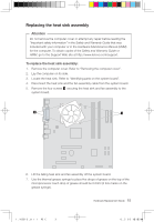
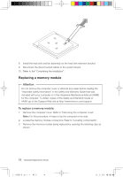
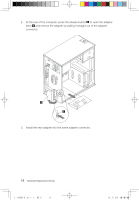
8. Install the heat sink and fan assembly on the heat sink retention bracket. 9. Reconnect the disconnected cables to the system board. 10. Refer to the" Completing the installation". Replacing a memory module Attention Do not remove the computer cover or attempt any repair before reading the "Important safety information" in the Safety and Warranty Guide that was included with your computer or in the Hardware Maintenance Manual (HMM) for the computer. To obtain copies of the Safety and Warranty Guide or HMM, go to the Support Web site at http://www.lenovo.com/support. To replace a memory module: 1. Remove the computer cover. Refer to "Removing the computer cover". Note: For this procedure, it helps to lay the computer on its side. 2. Locate the memory module connectors. Refer to "Locating components". 3. Remove the memory module being replaced by opening the retaining clips as shown. 16 Hardware Replacement Guide 31032753 IdeaCentre K_HRG_EN.indd 16 2007.12.7 3:41:55 PM
-
 1
1 -
2
-
3
-
4
-
5
-
6
-
7
-
8
-
9
-
10
-
11
-
12
-
 13
13 -
 14
14 -
 15
15 -
 16
16 -
 17
17 -
 18
18 -
 19
19 -
 20
20 -
 21
21 -
 22
22 -
 23
23 -
24
-
25
-
26
-
27
-
28
-
29
-
30
-
31
-
32
 |
 |
