Lenovo IdeaCentre K450 IdeaCentre K4 Series Hardware Maintenance Manual - Page 45
Step 10. Remove the Wi-Fi card. Refer to Replacing the Wi-Fi card.
 |
View all Lenovo IdeaCentre K450 manuals
Add to My Manuals
Save this manual to your list of manuals |
Page 45 highlights
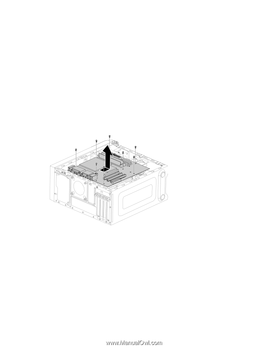
Step 2. Unplug all power cords from electrical outlets. Step 3. Disconnect all cables attached to the computer. This includes power cords, input/output (I/O) cables, and any other cables that are connected to the computer. Refer to "Left and right view" and "Rear view" for help with locating the various connectors. Step 4. Remove the computer cover. Refer to "Removing the computer cover". Step 5. Remove the memory module. Refer to "Replacing a memory module". Step 6. Remove the microprocessor fan. Refer to "Replacing the microprocessor fan". Step 7. Remove the heat-sink. Refer to "Replacing the heat-sink". Step 8. Remove the graphic card. Refer to "Replacing the graphic card". Step 9. Remove the TV-Tuner card. Refer to "Replacing the TV-Tuner card". Step 10. Remove the Wi-Fi card. Refer to "Replacing the Wi-Fi card". Step 11. Remove the CPU. Refer to "Replacing the CPU". Step 12. Disconnect the all cables from the connectors on motherboard. Step 13. Remove the 8 screws that secure the motherboard to the chassis. Step 14. Slide then lift the motherboard out of the chassis to remove it. Step 15. Install the new motherboard: a. Line up the holes on the new motherboard with mounting holes on the chassis and secure it with screws. b. Reattach the memory module, Wi-Fi card, CPU, and the heat-sink to the new motherboard. c. Connect the all cables to the new motherboard. d. Attach the graphic card and TV-Tuner card to the new motherboard. Step 16. Reattach the computer cover. Chapter 8. Replacing hardware 39
-
 1
1 -
2
-
3
-
4
-
5
-
6
-
7
-
8
-
9
-
10
-
11
-
12
-
13
-
14
-
15
-
16
-
17
-
18
-
19
-
20
-
21
-
22
-
23
-
24
-
25
-
26
-
27
-
28
-
29
-
30
-
31
-
32
-
33
-
34
-
35
-
36
-
37
-
38
-
39
-
 40
40 -
 41
41 -
 42
42 -
 43
43 -
 44
44 -
 45
45 -
 46
46 -
 47
47
 |
 |