Lenovo IdeaPad Z400 Touch Hardware Maintenance Manual - Page 84
Integrated camera, LCD cable and antenna assembly
 |
View all Lenovo IdeaPad Z400 Touch manuals
Add to My Manuals
Save this manual to your list of manuals |
Page 84 highlights
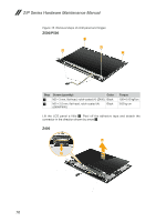
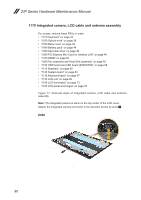
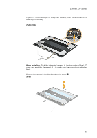
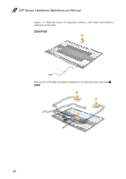
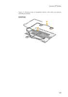
Z/P Series Hardware Maintenance Manual 1170 Integrated camera, LCD cable and antenna assembly For access, remove these FRUs in order: •• "1010 Keyboard" on page 33 •• "1020 Optical drive" on page 36 •• "1030 Base cover" on page 39 •• "1040 Battery pack" on page 44 •• "1050 Hard disk drive" on page 46 •• "1060 PCI Express Mini Card for wireless LAN" on page 48 •• "1070 DIMM" on page 50 •• "1080 Fan assembly and Heat Sink assembly" on page 52 •• "1100 ODD board and LED board (Z500/P500)" on page 58 •• "1110 Speakers" on page 60 •• "1120 System board" on page 63 •• "1130 Keyboard bezel" on page 67 •• "1140 LCD unit" on page 69 •• "1150 LCD front bezel" on page 73 •• "1160 LCD panel and hinges" on page 75 Figure 17. Removal steps of integrated camera, LCD cable and antenna assembly Note: The integrated camera is stuck on the top center of the LCD cover. Detach the integrated camera connector in the direction shown by arow 1. Z400 1 80
-
 1
1 -
2
-
3
-
4
-
5
-
6
-
7
-
8
-
9
-
10
-
11
-
12
-
13
-
14
-
15
-
16
-
17
-
18
-
19
-
20
-
21
-
22
-
23
-
24
-
25
-
26
-
27
-
28
-
29
-
30
-
31
-
32
-
33
-
34
-
35
-
36
-
37
-
38
-
39
-
40
-
41
-
42
-
43
-
44
-
45
-
46
-
47
-
48
-
49
-
50
-
51
-
52
-
53
-
54
-
55
-
56
-
57
-
58
-
59
-
60
-
61
-
62
-
63
-
64
-
65
-
66
-
67
-
68
-
69
-
70
-
71
-
72
-
73
-
74
-
75
-
76
-
77
-
78
-
 79
79 -
 80
80 -
 81
81 -
 82
82 -
 83
83 -
 84
84 -
 85
85 -
 86
86 -
 87
87 -
 88
88 -
 89
89 -
90
-
91
-
92
-
93
-
94
-
95
-
96
-
97
-
98
-
99
-
100
-
101
-
102
-
103
-
104
-
105
-
106
-
107
-
108
-
109
-
110
-
111
-
112
-
113
-
114
-
115
-
116
-
117
-
118
-
119
-
120
-
121
 |
 |