Lenovo IdeaPad Z400 Touch Hardware Maintenance Manual - Page 85
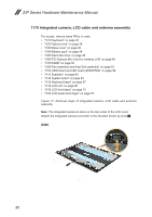
Removal steps of integrated camera, LCD cable and antenna, assembly continued
 |
View all Lenovo IdeaPad Z400 Touch manuals
Add to My Manuals
Save this manual to your list of manuals |
Page 85 highlights
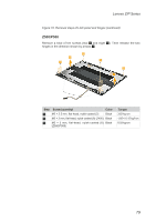
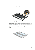
Lenovo Z/P Series Figure 17. Removal steps of integrated camera, LCD cable and antenna assembly (continued) Z500/P500 1 When installing: Stick the integrated camera to the top center of the LCD cover and ajust the placement of it to make sure the connector is attached firmly. Remove the camera in the direction shown by arrow 2. Z400 2 81
-
 1
1 -
2
-
3
-
4
-
5
-
6
-
7
-
8
-
9
-
10
-
11
-
12
-
13
-
14
-
15
-
16
-
17
-
18
-
19
-
20
-
21
-
22
-
23
-
24
-
25
-
26
-
27
-
28
-
29
-
30
-
31
-
32
-
33
-
34
-
35
-
36
-
37
-
38
-
39
-
40
-
41
-
42
-
43
-
44
-
45
-
46
-
47
-
48
-
49
-
50
-
51
-
52
-
53
-
54
-
55
-
56
-
57
-
58
-
59
-
60
-
61
-
62
-
63
-
64
-
65
-
66
-
67
-
68
-
69
-
70
-
71
-
72
-
73
-
74
-
75
-
76
-
77
-
78
-
79
-
 80
80 -
 81
81 -
 82
82 -
 83
83 -
 84
84 -
 85
85 -
 86
86 -
 87
87 -
 88
88 -
 89
89 -
 90
90 -
91
-
92
-
93
-
94
-
95
-
96
-
97
-
98
-
99
-
100
-
101
-
102
-
103
-
104
-
105
-
106
-
107
-
108
-
109
-
110
-
111
-
112
-
113
-
114
-
115
-
116
-
117
-
118
-
119
-
120
-
121
 |
 |
81
Lenovo Z/P Series
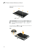
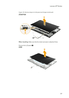
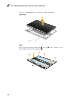
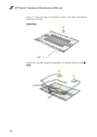
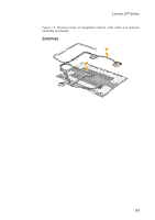
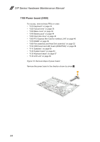
Figure 17. Removal steps of integrated camera, LCD cable and antenna
assembly (continued)
Z500/P500
1
When installing:
Stick the integrated camera to the top center of the LCD
cover and ajust the placement of it to make sure the connector is attached
firmly.
Remove the camera in the direction shown by arrow
2
.
Z400
2