Lenovo ThinkPad Edge E435 Hardware Maintenance Manual - Page 105
Wireless WAN MAIN antenna red
 |
View all Lenovo ThinkPad Edge E435 manuals
Add to My Manuals
Save this manual to your list of manuals |
Page 105 highlights
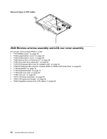
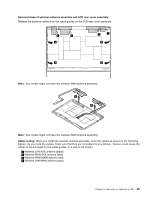
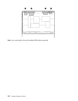
Removal steps of wireless antenna assembly and LCD rear cover assembly Release the antenna cables from the cable guides on the LCD rear cover assembly. 1 1 2 1 1 2 2 2 Note: Your model might not have the wireless WAN antenna assembly. 3 3 Note: Your model might not have the wireless WAN antenna assembly. Cable routing: When you install the wireless antenna assembly, route the cables as shown in the following figures. As you route the cables, make sure that they are not subject to any tension. Tension could cause the cables to be damaged by the cable guides, or a wire to be broken. a Wireless LAN AUX antenna (black) b Wireless WAN AUX antenna (blue) c Wireless WAN MAIN antenna (red) d Wireless LAN MAIN antenna (gray) Chapter 9. Removing or replacing a FRU 99
-
 1
1 -
2
-
3
-
4
-
5
-
6
-
7
-
8
-
9
-
10
-
11
-
12
-
13
-
14
-
15
-
16
-
17
-
18
-
19
-
20
-
21
-
22
-
23
-
24
-
25
-
26
-
27
-
28
-
29
-
30
-
31
-
32
-
33
-
34
-
35
-
36
-
37
-
38
-
39
-
40
-
41
-
42
-
43
-
44
-
45
-
46
-
47
-
48
-
49
-
50
-
51
-
52
-
53
-
54
-
55
-
56
-
57
-
58
-
59
-
60
-
61
-
62
-
63
-
64
-
65
-
66
-
67
-
68
-
69
-
70
-
71
-
72
-
73
-
74
-
75
-
76
-
77
-
78
-
79
-
80
-
81
-
82
-
83
-
84
-
85
-
86
-
87
-
88
-
89
-
90
-
91
-
92
-
93
-
94
-
95
-
96
-
97
-
98
-
99
-
 100
100 -
 101
101 -
 102
102 -
 103
103 -
 104
104 -
 105
105 -
 106
106 -
 107
107 -
 108
108 -
 109
109 -
 110
110
 |
 |
