Lenovo ThinkPad T450 (English) Hardware Maintenance Manual - ThinkPad T450 - Page 94
Systemboard
 |
View all Lenovo ThinkPad T450 manuals
Add to My Manuals
Save this manual to your list of manuals |
Page 94 highlights
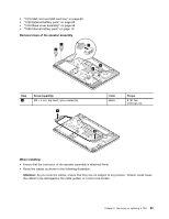
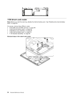
When installing: • Ensure that the connectors are attached firmly. • Route the cables as shown in step 8. Ensure that the cables are not subject to any tension. Tension could cause the cables to be damaged by the cable guides, or a wire to be broken. 1170 System board Important notices for handling the system board When handling the system board, read the following: • The system board has an accelerometer, which can be broken when several thousands of G-forces are applied. Note: Dropping a system board from a height of as little as 6 inches so that it falls flat on a hard bench can subject the accelerometer to as much as 6000 G's of shock. • Be careful not to drop the system board on a bench top that has a hard surface, such as metal, wood, or composite. • Avoid rough handling of any kind. • At every point in the process, be sure not to drop or stack the system board. • If you put a system board down, be sure to put it only on a padded surface such as an ESD mat or a corrugated conductive material. Note: Before you start the servicing, disable the internal battery pack. See "Disabling the internal battery pack" on page 60. For access, remove these FRUs in order: • "1010 SIM card and SIM-card tray" on page 60 • "1020 External battery pack" on page 60 • "1030 Keyboard" on page 61 • "1040 Base cover assembly" on page 68 • "1050 Hard disk drive or solid-state drive" on page 70 • "1060 Memory module" on page 72 • "1070 Wireless-LAN/Bluetooth card" on page 72 • "1080 Wireless-WAN card or M.2 solid-state drive" on page 73 • "1090 Internal battery pack" on page 75 • "1100 Coin-cell battery" on page 77 • "1120 Thermal fan assembly" on page 79 • "1160 LCD unit" on page 85 The following components soldered on the top side of the system board are extremely sensitive. When you service the system board, avoid any kind of rough handling. a Accelerometer chip for the hard disk drive Active Protection SystemTM b Microprocessor and Platform Controller Hub (PCH) c Graphics chip Note: The graphics chip c is only for discrete-graphics models. 88 Hardware Maintenance Manual
-
 1
1 -
2
-
3
-
4
-
5
-
6
-
7
-
8
-
9
-
10
-
11
-
12
-
13
-
14
-
15
-
16
-
17
-
18
-
19
-
20
-
21
-
22
-
23
-
24
-
25
-
26
-
27
-
28
-
29
-
30
-
31
-
32
-
33
-
34
-
35
-
36
-
37
-
38
-
39
-
40
-
41
-
42
-
43
-
44
-
45
-
46
-
47
-
48
-
49
-
50
-
51
-
52
-
53
-
54
-
55
-
56
-
57
-
58
-
59
-
60
-
61
-
62
-
63
-
64
-
65
-
66
-
67
-
68
-
69
-
70
-
71
-
72
-
73
-
74
-
75
-
76
-
77
-
78
-
79
-
80
-
81
-
82
-
83
-
84
-
85
-
86
-
87
-
88
-
 89
89 -
 90
90 -
 91
91 -
 92
92 -
 93
93 -
 94
94 -
 95
95 -
 96
96 -
 97
97 -
 98
98 -
 99
99 -
100
-
101
-
102
-
103
-
104
-
105
-
106
-
107
-
108
-
109
-
110
-
111
-
112
-
113
-
114
-
115
-
116
-
117
-
118
-
119
-
120
 |
 |
