Lenovo ThinkPad T61 Hardware Maintenance Manual - Page 104
Remove, cable, security, bracket, flat-head, nylon-coated, Black, kgfcm
 |
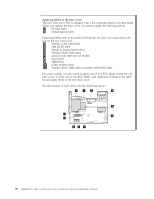
View all Lenovo ThinkPad T61 manuals
Add to My Manuals
Save this manual to your list of manuals |
Page 104 highlights
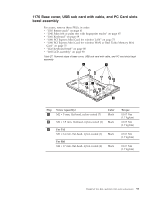
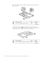
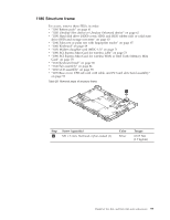
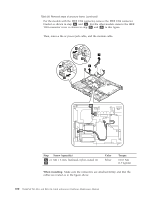
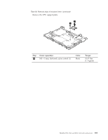
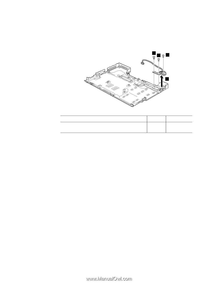
Table 27. Removal steps of base cover, USB sub card with cable, and PC card slots bezel assembly (continued) Remove the USB sub card with cable and the security hole bracket as in this figure. 1 1 1 2 Step 1 Screw (quantity) M2 × 3.5 mm, flat-head, nylon-coated (3) Color Black Torque 0.167 Nm (1.7 kgfcm) 96 ThinkPad T61, R61, and R61i (14.1-inch widescreen) Hardware Maintenance Manual
-
 1
1 -
2
-
3
-
4
-
5
-
6
-
7
-
8
-
9
-
10
-
11
-
12
-
13
-
14
-
15
-
16
-
17
-
18
-
19
-
20
-
21
-
22
-
23
-
24
-
25
-
26
-
27
-
28
-
29
-
30
-
31
-
32
-
33
-
34
-
35
-
36
-
37
-
38
-
39
-
40
-
41
-
42
-
43
-
44
-
45
-
46
-
47
-
48
-
49
-
50
-
51
-
52
-
53
-
54
-
55
-
56
-
57
-
58
-
59
-
60
-
61
-
62
-
63
-
64
-
65
-
66
-
67
-
68
-
69
-
70
-
71
-
72
-
73
-
74
-
75
-
76
-
77
-
78
-
79
-
80
-
81
-
82
-
83
-
84
-
85
-
86
-
87
-
88
-
89
-
90
-
91
-
92
-
93
-
94
-
95
-
96
-
97
-
98
-
 99
99 -
 100
100 -
 101
101 -
 102
102 -
 103
103 -
 104
104 -
 105
105 -
 106
106 -
 107
107 -
 108
108 -
 109
109 -
110
-
111
-
112
-
113
-
114
-
115
-
116
-
117
-
118
-
119
-
120
-
121
-
122
-
123
-
124
-
125
-
126
-
127
-
128
-
129
-
130
-
131
-
132
-
133
-
134
-
135
-
136
-
137
-
138
-
139
-
140
-
141
-
142
-
143
-
144
-
145
-
146
-
147
-
148
-
149
-
150
-
151
-
152
-
153
-
154
-
155
-
156
-
157
-
158
-
159
-
160
-
161
-
162
-
163
-
164
-
165
-
166
-
167
-
168
-
169
-
170
-
171
-
172
-
173
-
174
-
175
-
176
-
177
-
178
-
179
-
180
-
181
-
182
-
183
-
184
-
185
-
186
-
187
-
188
-
189
-
190
-
191
-
192
-
193
-
194
-
195
-
196
-
197
-
198
-
199
-
200
-
201
-
202
-
203
-
204
-
205
-
206
-
207
-
208
-
209
-
210
-
211
-
212
-
213
-
214
-
215
-
216
-
217
-
218
-
219
-
220
-
221
-
222
-
223
-
224
-
225
-
226
-
227
-
228
-
229
-
230
-
231
-
232
-
233
-
234
-
235
-
236
-
237
-
238
-
239
-
240
-
241
-
242
-
243
-
244
-
245
-
246
-
247
-
248
-
249
-
250
-
251
-
252
-
253
-
254
-
255
-
256
 |
 |
Table
27.
Removal
steps
of
base
cover,
USB
sub
card
with
cable,
and
PC
card
slots
bezel
assembly
(continued)
Remove
the
USB
sub
card
with
cable
and
the
security
hole
bracket
as
in
this
figure.
1
1
2
1
Step
Screw
(quantity)
Color
Torque
±1²
M2
×
3.5
mm,
flat-head,
nylon-coated
(3)
Black
0.167
Nm
(1.7
kgfcm)
96
ThinkPad
T61,
R61,
and
R61i
(14.1-inch
widescreen)
Hardware
Maintenance
Manual