Lenovo ThinkPad T61 Hardware Maintenance Manual - Page 116
double-faced
 |
View all Lenovo ThinkPad T61 manuals
Add to My Manuals
Save this manual to your list of manuals |
Page 116 highlights
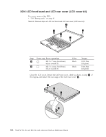
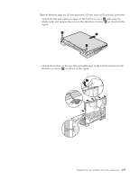
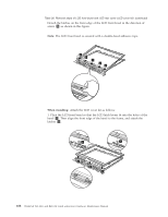
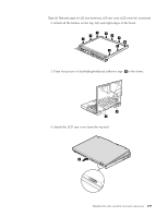
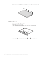
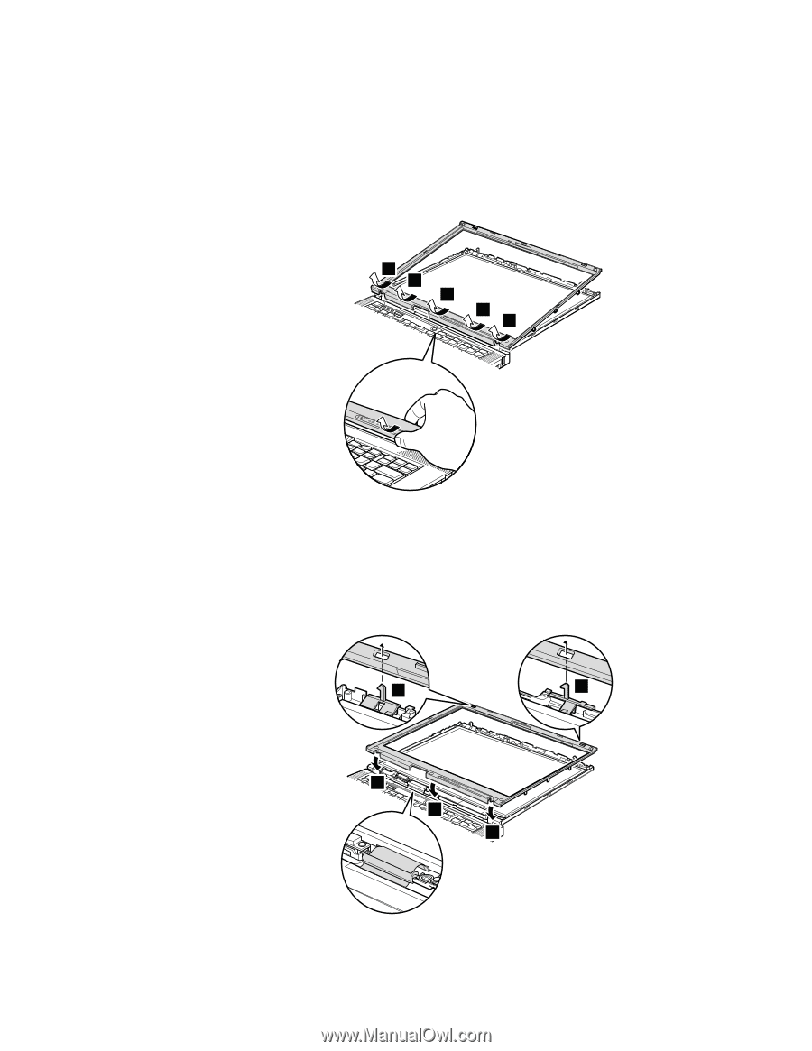
Table 30. Removal steps of LCD front bezel and LCD rear cover (LCD cover kit) (continued) Detach the latches on the front edge of the LCD front bezel in the direction of arrow 8 as shown in this figure. Note: The LCD front bezel is secured with a double-faced adhesive tape. 8 8 8 8 8 When installing: Attach the LCD cover kit as follows: 1. Place the LCD front bezel so that the LCD latch levers fit into the holes of the bezel 1 . Then align the front edge of the bezel to the frame, and attach the latches 2 . 1 1 2 2 2 108 ThinkPad T61, R61, and R61i (14.1-inch widescreen) Hardware Maintenance Manual
-
 1
1 -
2
-
3
-
4
-
5
-
6
-
7
-
8
-
9
-
10
-
11
-
12
-
13
-
14
-
15
-
16
-
17
-
18
-
19
-
20
-
21
-
22
-
23
-
24
-
25
-
26
-
27
-
28
-
29
-
30
-
31
-
32
-
33
-
34
-
35
-
36
-
37
-
38
-
39
-
40
-
41
-
42
-
43
-
44
-
45
-
46
-
47
-
48
-
49
-
50
-
51
-
52
-
53
-
54
-
55
-
56
-
57
-
58
-
59
-
60
-
61
-
62
-
63
-
64
-
65
-
66
-
67
-
68
-
69
-
70
-
71
-
72
-
73
-
74
-
75
-
76
-
77
-
78
-
79
-
80
-
81
-
82
-
83
-
84
-
85
-
86
-
87
-
88
-
89
-
90
-
91
-
92
-
93
-
94
-
95
-
96
-
97
-
98
-
99
-
100
-
101
-
102
-
103
-
104
-
105
-
106
-
107
-
108
-
109
-
110
-
 111
111 -
 112
112 -
 113
113 -
 114
114 -
 115
115 -
 116
116 -
 117
117 -
 118
118 -
 119
119 -
 120
120 -
 121
121 -
122
-
123
-
124
-
125
-
126
-
127
-
128
-
129
-
130
-
131
-
132
-
133
-
134
-
135
-
136
-
137
-
138
-
139
-
140
-
141
-
142
-
143
-
144
-
145
-
146
-
147
-
148
-
149
-
150
-
151
-
152
-
153
-
154
-
155
-
156
-
157
-
158
-
159
-
160
-
161
-
162
-
163
-
164
-
165
-
166
-
167
-
168
-
169
-
170
-
171
-
172
-
173
-
174
-
175
-
176
-
177
-
178
-
179
-
180
-
181
-
182
-
183
-
184
-
185
-
186
-
187
-
188
-
189
-
190
-
191
-
192
-
193
-
194
-
195
-
196
-
197
-
198
-
199
-
200
-
201
-
202
-
203
-
204
-
205
-
206
-
207
-
208
-
209
-
210
-
211
-
212
-
213
-
214
-
215
-
216
-
217
-
218
-
219
-
220
-
221
-
222
-
223
-
224
-
225
-
226
-
227
-
228
-
229
-
230
-
231
-
232
-
233
-
234
-
235
-
236
-
237
-
238
-
239
-
240
-
241
-
242
-
243
-
244
-
245
-
246
-
247
-
248
-
249
-
250
-
251
-
252
-
253
-
254
-
255
-
256
 |
 |
Table
30.
Removal
steps
of
LCD
front
bezel
and
LCD
rear
cover
(LCD
cover
kit)
(continued)
Detach
the
latches
on
the
front
edge
of
the
LCD
front
bezel
in
the
direction
of
arrow
±8²
as
shown
in
this
figure.
Note:
The
LCD
front
bezel
is
secured
with
a
double-faced
adhesive
tape.
8
8
8
8
8
When
installing:
Attach
the
LCD
cover
kit
as
follows:
1.
Place
the
LCD
front
bezel
so
that
the
LCD
latch
levers
fit
into
the
holes
of
the
bezel
±1²
.
Then
align
the
front
edge
of
the
bezel
to
the
frame,
and
attach
the
latches
±2²
.
2
2
2
1
1
108
ThinkPad
T61,
R61,
and
R61i
(14.1-inch
widescreen)
Hardware
Maintenance
Manual