Lenovo ThinkPad X220i Hardware Maintenance Manual - Page 103
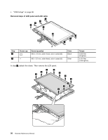
LCD panel and LCD cable
 |
View all Lenovo ThinkPad X220i manuals
Add to My Manuals
Save this manual to your list of manuals |
Page 103 highlights
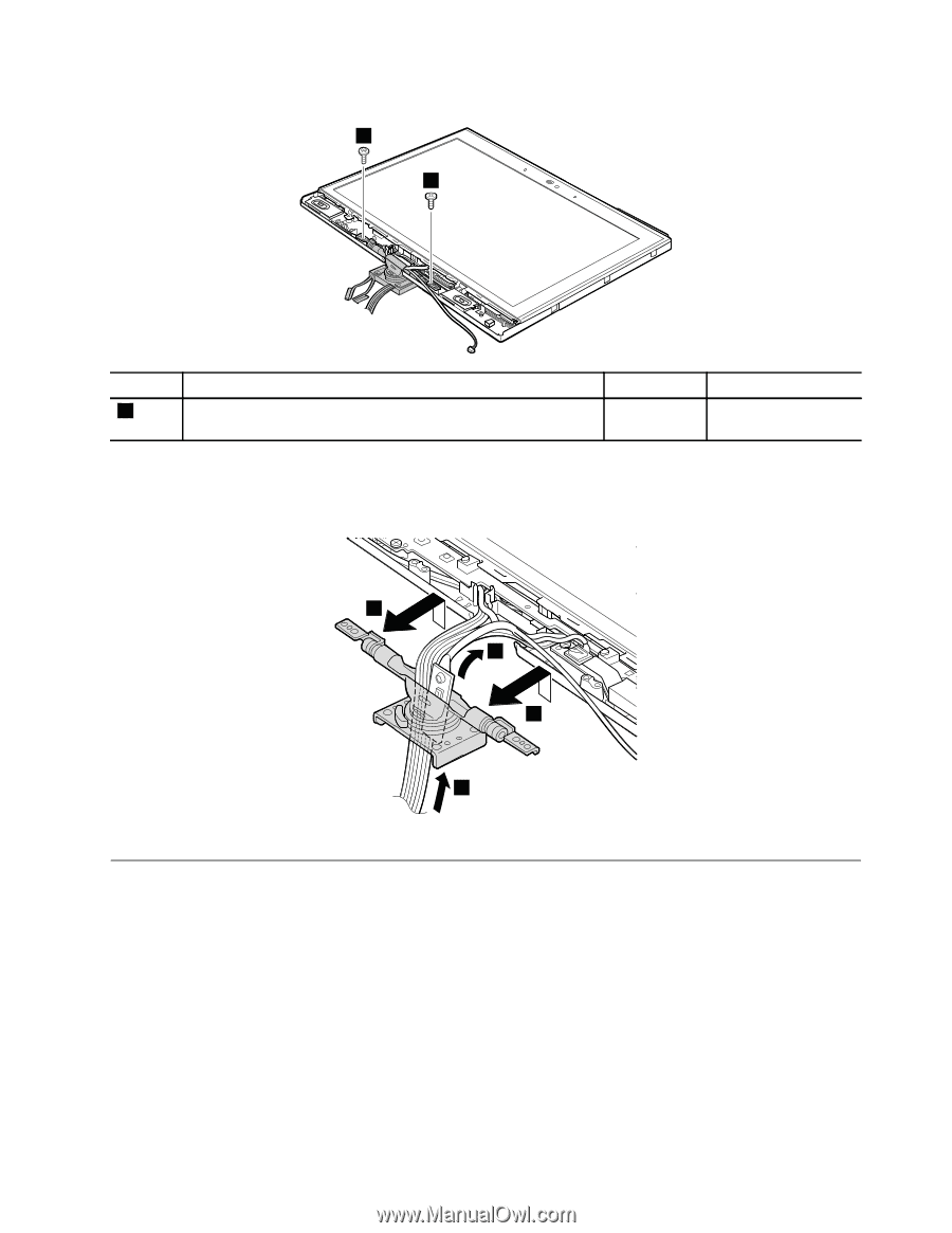
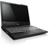
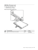
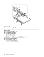
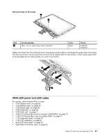
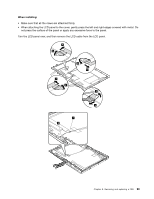
Removal steps of the hinge 1 1 Step 1 Screw (quantity) M2.5 × 6 mm, wafer-head, nylon-coated (2) Color Black Torque 0.392 Nm (4 kgfcm) Detach the hinge from the LCD rear cover, and gently pull the cables out through the guide hole in the hinge. Pull them all at once. As you pull them, be sure not to subject them to any tension, which could cause them to be damaged by the cable guides, or a wire to be broken. 2 3 2 3 2040 LCD panel and LCD cable For access, remove these FRUs in order: • "1010 Digitizer pen" on page 63 • "1020 Battery pack" on page 63 • "1050 Hinge caps" on page 68 • "1060 Keyboard" on page 68 • "1070 Palm rest" on page 71 • "1090 PCI Express Mini Card for wireless LAN/WiMAX" on page 75 • "1100 PCI Express Mini Card for wireless WAN" on page 77 • "1120 Keyboard bezel" on page 79 • "1130 LCD assembly" on page 81 • "2010 LCD front bezel" on page 93 • "2020 Micro-Processor card" on page 95 Chapter 8. Removing and replacing a FRU 97
-
 1
1 -
2
-
3
-
4
-
5
-
6
-
7
-
8
-
9
-
10
-
11
-
12
-
13
-
14
-
15
-
16
-
17
-
18
-
19
-
20
-
21
-
22
-
23
-
24
-
25
-
26
-
27
-
28
-
29
-
30
-
31
-
32
-
33
-
34
-
35
-
36
-
37
-
38
-
39
-
40
-
41
-
42
-
43
-
44
-
45
-
46
-
47
-
48
-
49
-
50
-
51
-
52
-
53
-
54
-
55
-
56
-
57
-
58
-
59
-
60
-
61
-
62
-
63
-
64
-
65
-
66
-
67
-
68
-
69
-
70
-
71
-
72
-
73
-
74
-
75
-
76
-
77
-
78
-
79
-
80
-
81
-
82
-
83
-
84
-
85
-
86
-
87
-
88
-
89
-
90
-
91
-
92
-
93
-
94
-
95
-
96
-
97
-
 98
98 -
 99
99 -
 100
100 -
 101
101 -
 102
102 -
 103
103 -
 104
104 -
 105
105 -
 106
106 -
 107
107 -
 108
108 -
109
-
110
-
111
-
112
-
113
-
114
-
115
-
116
-
117
-
118
-
119
-
120
-
121
-
122
-
123
-
124
-
125
-
126
-
127
-
128
-
129
-
130
-
131
-
132
-
133
-
134
-
135
-
136
-
137
-
138
-
139
-
140
-
141
-
142
-
143
-
144
-
145
-
146
-
147
-
148
-
149
-
150
 |
 |