Lenovo ThinkPad X220i Hardware Maintenance Manual - Page 90
DC-in connector, base cover, fan, digitizer pen case, and pen switch assembly
 |
View all Lenovo ThinkPad X220i manuals
Add to My Manuals
Save this manual to your list of manuals |
Page 90 highlights
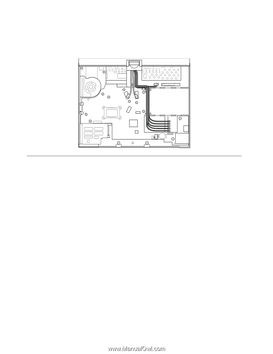
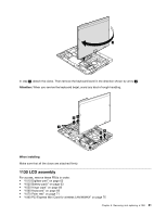
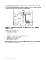
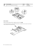
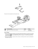
• Make sure that you route the cables correctly and you tape up the cables in the proper positions as shown in the following figure. • When you route the cables, make sure that they are not subjected to any tension. Tension could cause the cables to be damaged by the cable guides, or a wire to be broken. 1140 DC-in connector, base cover, fan, digitizer pen case, and pen switch assembly For access, remove these FRUs in order: • "1010 Digitizer pen" on page 63 • "1020 Battery pack" on page 63 • "1050 Hinge caps" on page 68 • "1060 Keyboard" on page 68 • "1070 Palm rest" on page 71 • "1090 PCI Express Mini Card for wireless LAN/WiMAX" on page 75 • "1100 PCI Express Mini Card for wireless WAN" on page 77 • "1110 Bluetooth daughter card" on page 78 • "1120 Keyboard bezel" on page 79 • "1130 LCD assembly" on page 81 Removal steps of DC-in connector, base cover, fan, digitizer pen case, and pen switch assembly Remove the top shielding assembly at first. 84 Hardware Maintenance Manual
-
 1
1 -
2
-
3
-
4
-
5
-
6
-
7
-
8
-
9
-
10
-
11
-
12
-
13
-
14
-
15
-
16
-
17
-
18
-
19
-
20
-
21
-
22
-
23
-
24
-
25
-
26
-
27
-
28
-
29
-
30
-
31
-
32
-
33
-
34
-
35
-
36
-
37
-
38
-
39
-
40
-
41
-
42
-
43
-
44
-
45
-
46
-
47
-
48
-
49
-
50
-
51
-
52
-
53
-
54
-
55
-
56
-
57
-
58
-
59
-
60
-
61
-
62
-
63
-
64
-
65
-
66
-
67
-
68
-
69
-
70
-
71
-
72
-
73
-
74
-
75
-
76
-
77
-
78
-
79
-
80
-
81
-
82
-
83
-
84
-
 85
85 -
 86
86 -
 87
87 -
 88
88 -
 89
89 -
 90
90 -
 91
91 -
 92
92 -
 93
93 -
 94
94 -
 95
95 -
96
-
97
-
98
-
99
-
100
-
101
-
102
-
103
-
104
-
105
-
106
-
107
-
108
-
109
-
110
-
111
-
112
-
113
-
114
-
115
-
116
-
117
-
118
-
119
-
120
-
121
-
122
-
123
-
124
-
125
-
126
-
127
-
128
-
129
-
130
-
131
-
132
-
133
-
134
-
135
-
136
-
137
-
138
-
139
-
140
-
141
-
142
-
143
-
144
-
145
-
146
-
147
-
148
-
149
-
150
 |
 |