Lenovo U300e Laptop IdeaPad U300e Hardware Maintenance Manual - Page 47
Screw quantity, Color, Torque, Make sure that all the connectors are attached firmly.
 |
View all Lenovo U300e Laptop manuals
Add to My Manuals
Save this manual to your list of manuals |
Page 47 highlights
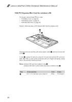
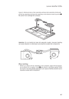
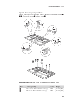
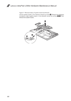
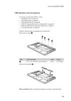
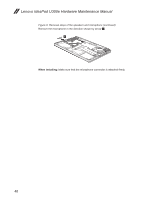
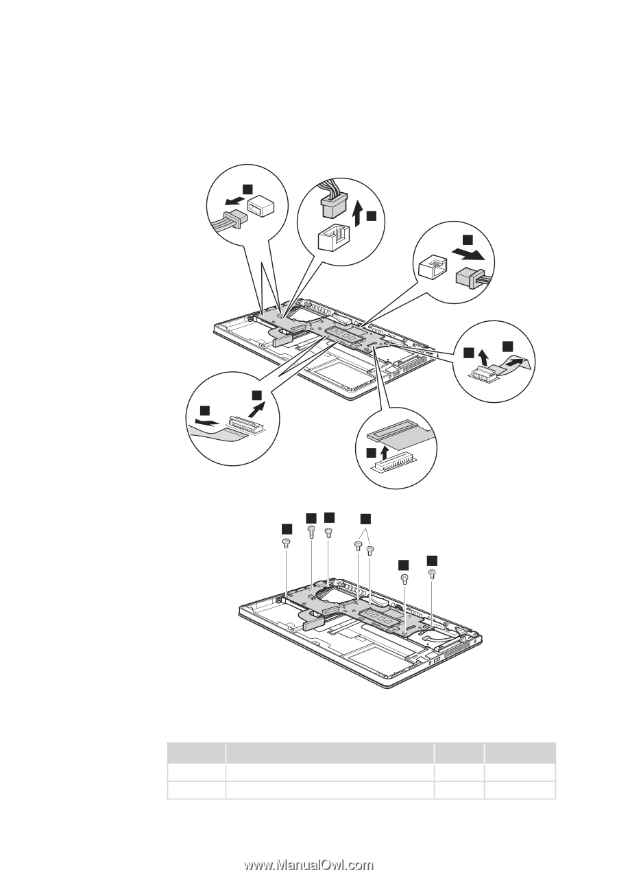
Lenovo IdeaPad U300e Figure 7. Removal steps of system board Detach eight connectors on system board in the direction shown by arrows 1 2 3. Remove six screws 4 and one screw 5. 2 3 2 1 2 2 1 3 54 4 4 4 4 When installing: Make sure that all the connectors are attached firmly. Step 4 5 Screw (quantity) M2 × 2.5 mm, flat-head, nylok-coated (6) M2 × 5 mm, flat-head, nylok-coated (1) Color White White Torque 1.5 ± 0.2 kgfcm 1.5 ± 0.2 kgfcm 43
-
 1
1 -
2
-
3
-
4
-
5
-
6
-
7
-
8
-
9
-
10
-
11
-
12
-
13
-
14
-
15
-
16
-
17
-
18
-
19
-
20
-
21
-
22
-
23
-
24
-
25
-
26
-
27
-
28
-
29
-
30
-
31
-
32
-
33
-
34
-
35
-
36
-
37
-
38
-
39
-
40
-
41
-
 42
42 -
 43
43 -
 44
44 -
 45
45 -
 46
46 -
 47
47 -
 48
48 -
 49
49 -
 50
50 -
 51
51 -
 52
52 -
53
-
54
-
55
-
56
-
57
-
58
-
59
-
60
-
61
-
62
-
63
-
64
-
65
-
66
-
67
-
68
-
69
-
70
-
71
-
72
-
73
 |
 |
43
Lenovo IdeaPad U300e
Figure 7. Removal steps of system board
Detach eight connectors on system board in the direction shown by arrows
1
2
3
. Remove six screws
4
and one screw
5
.
2
3
2
1
2
1
2
3
4
4
4
4
4
5
When installing:
Make sure that all the connectors are attached firmly.
Step
Screw (quantity)
Color
Torque
4
M2 × 2.5 mm, flat-head, nylok-coated (6)
White
1.5 ± 0.2 kgfcm
5
M2 × 5 mm, flat-head, nylok-coated (1)
White
1.5 ± 0.2 kgfcm