Lenovo U300e Laptop IdeaPad U300e Hardware Maintenance Manual - Page 52
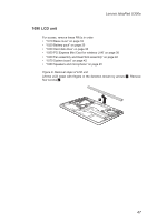
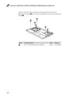
Remove the LCD unit in the direction shown by arrows, the LCD cable along the cable guides.
 |
View all Lenovo U300e Laptop manuals
Add to My Manuals
Save this manual to your list of manuals |
Page 52 highlights
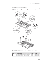
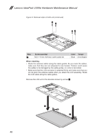
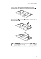
Lenovo IdeaPad U300e Hardware Maintenance Manual Figure 9. Removal steps of LCD unit (continued) 2 2 22 Step 2 Screw (quantity) M2.5 × 6 mm, flat-head, nylok-coated (4) Color Torque Black 3.0 ± 0.2 kgfcm When installing: •• Route the antenna cables along the cable guides. As you route the cables, make sure that they are not subjected to any tension. Tension could cause the cables to be damaged by the cable guides, or a wire to be broken. •• Make sure that the LCD connector is attached firmly and make sure that you do not pinch the antenna cables when you attach the LCD assembly. Route the LCD cable along the cable guides. Remove the LCD unit in the direction shown by arrows 3. 3 3 48
-
 1
1 -
2
-
3
-
4
-
5
-
6
-
7
-
8
-
9
-
10
-
11
-
12
-
13
-
14
-
15
-
16
-
17
-
18
-
19
-
20
-
21
-
22
-
23
-
24
-
25
-
26
-
27
-
28
-
29
-
30
-
31
-
32
-
33
-
34
-
35
-
36
-
37
-
38
-
39
-
40
-
41
-
42
-
43
-
44
-
45
-
46
-
 47
47 -
 48
48 -
 49
49 -
 50
50 -
 51
51 -
 52
52 -
 53
53 -
 54
54 -
 55
55 -
 56
56 -
 57
57 -
58
-
59
-
60
-
61
-
62
-
63
-
64
-
65
-
66
-
67
-
68
-
69
-
70
-
71
-
72
-
73
 |
 |
48
Lenovo IdeaPad U300e Hardware Maintenance Manual
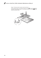
Figure 9. Removal steps of LCD unit
(continued)
2
2
2
2
Step
Screw (quantity)
Color
Torque
2
M2.5 × 6 mm, flat-head, nylok-coated (4)
Black
3.0 ± 0.2 kgfcm
When installing:
Route the antenna cables along the cable guides. As you route the cables,
•
make sure that they are not subjected to any tension. Tension could cause
the cables to be damaged by the cable guides, or a wire to be broken.
Make sure that the LCD connector is attached firmly and make sure that you
•
do not pinch the antenna cables when you attach the LCD assembly. Route
the LCD cable along the cable guides.
Remove the LCD unit in the direction shown by arrows
3
.
3
3