Lenovo U300e Laptop IdeaPad U300e Hardware Maintenance Manual - Page 56
Remove four screws, then remove two brackets in the direction shown by, arrows, continued
 |
View all Lenovo U300e Laptop manuals
Add to My Manuals
Save this manual to your list of manuals |
Page 56 highlights
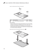
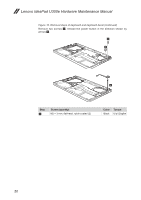
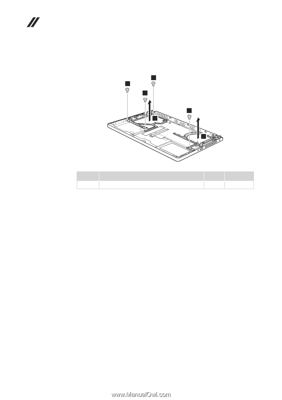
Lenovo IdeaPad U300e Hardware Maintenance Manual Figure 10. Removal steps of keyboard and keyboard bezel (continued) Remove four screws 8, then remove two brackets in the direction shown by arrows 9. 8 8 8 8 9 9 Step 8 Screw (quantity) M2 × 3 mm, flat-head, nylok-coated (4) Color Torque Black 1.5 ± 0.2 kgfcm 52
-
 1
1 -
2
-
3
-
4
-
5
-
6
-
7
-
8
-
9
-
10
-
11
-
12
-
13
-
14
-
15
-
16
-
17
-
18
-
19
-
20
-
21
-
22
-
23
-
24
-
25
-
26
-
27
-
28
-
29
-
30
-
31
-
32
-
33
-
34
-
35
-
36
-
37
-
38
-
39
-
40
-
41
-
42
-
43
-
44
-
45
-
46
-
47
-
48
-
49
-
50
-
 51
51 -
 52
52 -
 53
53 -
 54
54 -
 55
55 -
 56
56 -
 57
57 -
 58
58 -
 59
59 -
 60
60 -
 61
61 -
62
-
63
-
64
-
65
-
66
-
67
-
68
-
69
-
70
-
71
-
72
-
73
 |
 |
52
Lenovo IdeaPad U300e Hardware Maintenance Manual
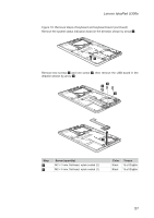
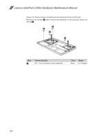
Figure 10. Removal steps of keyboard and keyboard bezel
(continued)
Remove four screws
8
, then remove two brackets in the direction shown by
arrows
9
.
8
8
8
8
9
9
Step
Screw (quantity)
Color
Torque
8
M2 × 3 mm, flat-head, nylok-coated (4)
Black
1.5 ± 0.2 kgfcm