Lenovo Yoga 2-1051 (English) Hardware Maintenance Manual - Yoga Tablet 2 1051F - Page 57
Main board, Main FPC see Step 3 on in 1060 Main FPC
 |
View all Lenovo Yoga 2-1051 manuals
Add to My Manuals
Save this manual to your list of manuals |
Page 57 highlights
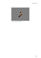
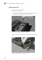
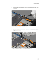
Lenovo 1051 1090 Main board Important notices for handling PCB: When handling PCB, bear the following in mind: • Be careful not to drop the PCB onto a bench top that has a hard surface, such as surface made of metal, wood, or composite materials. • Avoid rough handling of any kind. • Make sure not to drop or stack the PCB in the whole process. • Make sure to put the PCB only on surface covered with such materials as an ESD mat or conductive corrugated plate. For access, remove the following FRU: • "1010 Rear cover" on page 28 and Detach the following FPCs from the main board: • Battery FPC (see Step 1 on page 31 in "1020 Right speaker") • LCD FPC (see Step 2 on page 41 and Step 4 on page 42 in "1050 LCD FPC") • Main FPC (see Step 3 on page 45 in "1060 Main FPC") • HDMI FPC (see Step 3 on page 48 in "1070 HDMI FPC" 1. Unlock the connector of the TP FPC on the main board using a guitar pick as shown in the figure below. Figure 9-1. Unlocking the connector of the TP FPC 53
-
 1
1 -
2
-
3
-
4
-
5
-
6
-
7
-
8
-
9
-
10
-
11
-
12
-
13
-
14
-
15
-
16
-
17
-
18
-
19
-
20
-
21
-
22
-
23
-
24
-
25
-
26
-
27
-
28
-
29
-
30
-
31
-
32
-
33
-
34
-
35
-
36
-
37
-
38
-
39
-
40
-
41
-
42
-
43
-
44
-
45
-
46
-
47
-
48
-
49
-
50
-
51
-
 52
52 -
 53
53 -
 54
54 -
 55
55 -
 56
56 -
 57
57 -
 58
58 -
 59
59 -
 60
60 -
 61
61 -
 62
62 -
63
-
64
-
65
-
66
-
67
-
68
-
69
-
70
-
71
-
72
-
73
-
74
-
75
-
76
-
77
-
78
-
79
-
80
-
81
-
82
-
83
-
84
-
85
-
86
-
87
-
88
-
89
-
90
-
91
-
92
-
93
 |
 |