Lenovo Yoga 2-1051 (English) Hardware Maintenance Manual - Yoga Tablet 2 1051F - Page 60
on the main board as shown in the below
 |
View all Lenovo Yoga 2-1051 manuals
Add to My Manuals
Save this manual to your list of manuals |
Page 60 highlights
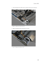
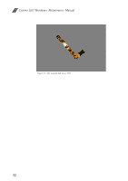
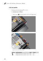
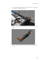
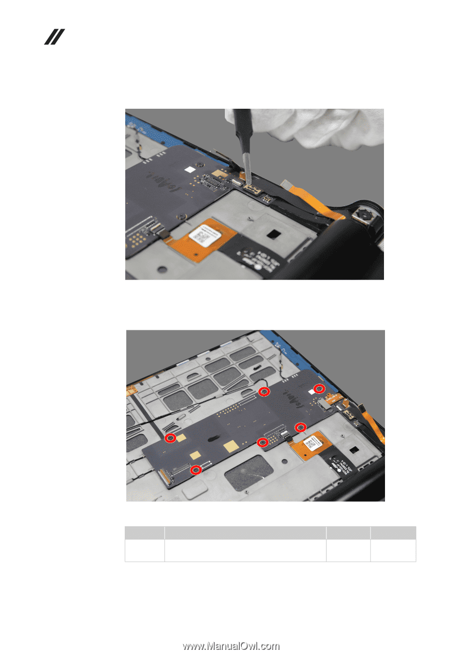
Lenovo 1051 Hardware Maintenance Manual 6. Detach the connector of the rear camera FPC from the main board using a pair of tweezers. Figure 9-6. Detaching the connector of the rear camera FPC 7. Remove screws a on the main board as shown in the figure below. Figure 9-7. The screws on the main board Part No. Screw (quantity) a Phillips flat head screw, M1.4 × 1.3, wide head (6) Color Black Torque N/A 56
-
 1
1 -
2
-
3
-
4
-
5
-
6
-
7
-
8
-
9
-
10
-
11
-
12
-
13
-
14
-
15
-
16
-
17
-
18
-
19
-
20
-
21
-
22
-
23
-
24
-
25
-
26
-
27
-
28
-
29
-
30
-
31
-
32
-
33
-
34
-
35
-
36
-
37
-
38
-
39
-
40
-
41
-
42
-
43
-
44
-
45
-
46
-
47
-
48
-
49
-
50
-
51
-
52
-
53
-
54
-
 55
55 -
 56
56 -
 57
57 -
 58
58 -
 59
59 -
 60
60 -
 61
61 -
 62
62 -
 63
63 -
 64
64 -
 65
65 -
66
-
67
-
68
-
69
-
70
-
71
-
72
-
73
-
74
-
75
-
76
-
77
-
78
-
79
-
80
-
81
-
82
-
83
-
84
-
85
-
86
-
87
-
88
-
89
-
90
-
91
-
92
-
93
 |
 |
Lenovo 1051 Hardware Maintenance Manual
56
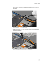
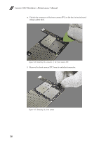
6.
Detach the connector of the rear camera FPC from the main board using a
pair of tweezers.
Figure 9-6. Detaching the connector of the rear camera FPC
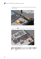
7.
Remove screws
on the main board as shown in the figure below.
Figure 9-7. The screws on the main board
Part No.
Screw (quantity)
Color
Torque
Phillips flat head screw, M1.4 × 1.3, wide
head (6)
Black
N/A
a
a