Lexmark XC4143 Printer Languages and Interfaces Technical Reference - Page 141
Serial communication parameters RS-232C, Standard Serial Error, Serial Option [x] Error
 |
View all Lexmark XC4143 manuals
Add to My Manuals
Save this manual to your list of manuals |
Page 141 highlights
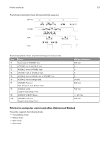
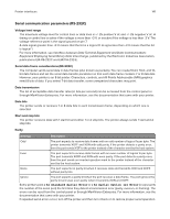
Printer interfaces 141 Serial communication parameters (RS-232C) Voltage level range The maximum voltage level for control lines or data lines is +/- 25 positive V dc and +/- 25 negative V dc. A timing or control line is active if the voltage is more than +3 V, or inactive if the voltage is less than -3 V. The voltage reference point is the signal ground on pin 7. A data signal greater than +3 V means that the bit is a logical 0. A signal less than -3 V means that the bit is logical 1. For more information, see Interface between Data Terminal Equipment and Data Communications Equipment Employing Serial Binary Data Interchange, published by the Electronic Industries Association, publications EIA RS-232C and EIA\TIA-232-E. Serial data frame considerations (RS-232C) The computer sends serial data in data frames (also known as packets). You can create 10-bit, 11-bit, and 12bit data frames and set the serial data transfer parameter so that each data frame contains 7 or 8 data bits. However, your printer is an 8-bit printer. Characters, controls, and All Points Addressable (APA) graphics need 8 bits of data. If you select 7-bit data transfer, some unexpected characters may print. Data transmission The list of acceptable data transfer rates (in bits per second) can be accessed from the control panel or through MarkVision Enterprise. For more information, see the documentation that came with your printer. Data bits The printer sends or receives 7 or 8 data bits in each transmission frame, depending on which one is selected. Start and stop bits The printer receives data with 1 start bit and either 1 or 2 stop bits. The printer always sends 1 start and 2 stop bits. Parity Settings Description Odd The port expects to receive data frames with an odd number of logical 1s per byte. The printer transmits XOFF and XON with odd parity. If the printer detects a parity error, then the port sends X'5F' to the printer instead of the character sent by the host system. Even The port expects to receive data frames with an even number of logical 1s per byte. The port transmits XOFF and XON with even parity. If the port detects a parity error, then the port sends an inverted question mark to the printer instead of the character sent by the host system. None The port expects no parity bit when it receives data and transmits XON and XOFF without parity bits. Ignore The port expects a parity bit when the port receives a data frame. The port ignores the parity bit and uses even parity when it transmits XON and XOFF. Some printers post a 54 Standard Serial Error or a 54 Serial Option [x] Error (x represents the number of the serial port) the first time they detect a transmission error (parity, overrun, or framing). The errors can be reset from the control panel or through MarkVision Enterprise. For more information, see the documentation that came with your printer. If repeated serial errors occur, turn off the printer and then turn it back on to restore proper serial operation.
-
 1
1 -
2
-
3
-
4
-
5
-
6
-
7
-
8
-
9
-
10
-
11
-
12
-
13
-
14
-
15
-
16
-
17
-
18
-
19
-
20
-
21
-
22
-
23
-
24
-
25
-
26
-
27
-
28
-
29
-
30
-
31
-
32
-
33
-
34
-
35
-
36
-
37
-
38
-
39
-
40
-
41
-
42
-
43
-
44
-
45
-
46
-
47
-
48
-
49
-
50
-
51
-
52
-
53
-
54
-
55
-
56
-
57
-
58
-
59
-
60
-
61
-
62
-
63
-
64
-
65
-
66
-
67
-
68
-
69
-
70
-
71
-
72
-
73
-
74
-
75
-
76
-
77
-
78
-
79
-
80
-
81
-
82
-
83
-
84
-
85
-
86
-
87
-
88
-
89
-
90
-
91
-
92
-
93
-
94
-
95
-
96
-
97
-
98
-
99
-
100
-
101
-
102
-
103
-
104
-
105
-
106
-
107
-
108
-
109
-
110
-
111
-
112
-
113
-
114
-
115
-
116
-
117
-
118
-
119
-
120
-
121
-
122
-
123
-
124
-
125
-
126
-
127
-
128
-
129
-
130
-
131
-
132
-
133
-
134
-
135
-
 136
136 -
 137
137 -
 138
138 -
 139
139 -
 140
140 -
 141
141 -
 142
142 -
 143
143 -
 144
144 -
 145
145 -
 146
146 -
147
-
148
 |
 |