LiftMaster HS670 HS670 GL BOARD Manual - Page 11
Gate Stops, Suspension System, Manual Operation, Important
 |
View all LiftMaster HS670 manuals
Add to My Manuals
Save this manual to your list of manuals |
Page 11 highlights
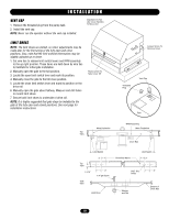
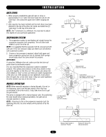
I N S TA L L AT I O N GATE STOPS 1. When properly installed the gate will open or close in approximately 3" to 4" after limit shoe shuts the unit off, the "gate stop" will contact the upper drive wheel stopping the gate. 2. After operator has been installed and the limit shoes have been attached to the top of the drive rail, locate and install the (2) "gate stops" to the top of the drive rail. NOTE: The 7" dimension is a reference. You may have to adjust this slightly for your particular application. SUSPENSION SYSTEM 1. The suspension system is semi-factory set; simply loosen the suspension separator bolt completely. This will allow both wheels to pinch the drive rail. NOTE: It is suggested that the separator bolt be removed and left with unit. If it is not removed, make sure that it can not interfere with suspension system. 2. If more or less pressure is required, adjust both upper and lower suspension spring lock nuts as desired. Both springs should apply about the same amount of pressure. IMPORTANT: If using the LiftMaster drive rail, make sure that the drive rail guide wheel is positioned properly. It is very important that the suspension system is adjusted properly. This system puts pressure on the drive wheels so they can pinch together on the drive rail. This system also allows the drive wheels to "float" so they can follow any slight misalignment of the drive rail. If the springs are over tightened, it will reduce their life span. But, on the other hand, if they are under tightened, the drive wheels may slip on the drive rail. MANUAL OPERATION NOTE: When manually opening or closing the gate, it is not, in the beginning, easy to get the gate started. Since fluid has accumulated in the drive motors, it may take more force to get the gate started. The pump is equipped with a manual bypass valve. By positioning the valve handle down (manual operation), the gate can be manually opened or closed. NOTE: A back-up to this is the suspension separator bolt. By tightening this bolt, the drive wheels will be pushed off by the drive rail. Gate Stops Limit Shoe Limit Shoe 11/16" Screw Gate Stop Lockwasher 11/16" Hex Nut Limit Shoe Upper Drive Wheel Separator Bolt (Use 9/16" Socket) Lock Adjustment Lower Nut (Use 3/4" Wrench) Guide Wheel (provided on operator for use with LiftMaster Drive Rail) Upper Drive Wheel Drive Rail Guide Wheel Lower Drive Wheel Bypass Valve Handle In Automatic Position Rotate 90° (Down) For Manual Operation 11
-
 1
1 -
2
-
3
-
4
-
5
-
 6
6 -
 7
7 -
 8
8 -
 9
9 -
 10
10 -
 11
11 -
 12
12 -
 13
13 -
 14
14 -
 15
15 -
 16
16 -
17
-
18
-
19
-
20
-
21
-
22
-
23
-
24
-
25
-
26
-
27
-
28
-
29
-
30
-
31
-
32
-
33
-
34
-
35
-
36
 |
 |
