LiftMaster HS670 HS670 GL BOARD Manual - Page 32
Electrical Box, Individual Parts And Kits - model
 |
View all LiftMaster HS670 manuals
Add to My Manuals
Save this manual to your list of manuals |
Page 32 highlights
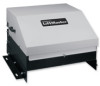
ELECTRICAL BOX COMPLETE ELECTRICAL BOX REPLACEMENT KITS To order a complete electrical box replacement kit, add a Kprefix to the model number of your operator. For example: HS670-100-21 (Operator) = K-HS670-100-21 (Electrical Box Kit) 3 5 7 10 2 13 8 15 6 12 9 9 14 11 1 4 ITEM 1 2 3 4 5 6 7 8 9 10 11 12 13 14 15 PART # K001A5566 03-8024-K 10-19198 10-19199 21-3260-1 31-13703 35-310-032 G71-416-7NH 42-114-2 42-19200 42-8116-1 74-19201 23-3001 23-3005 31-G055 25-2015 25-2006 INDIVIDUAL PARTS AND KITS DESCRIPTION QTY Control Board 1 Contactor, 3 Pole Reversing 1 Control Box Cover 1 Mounting Bracket 1 Transformer, 50/60HO, 60VA 1 Standoffs for Optional Loop Detector 8 Fuse, Glass Body 3.2AMP 3AG 1 Loop Detector 2 Terminal Strip, 14 Poles 1 Radio Block 4 Pole 1 Terminal Strip, PCB 16 Pole 1 Control Box 1 Switch 1n 1 Switch 3n Standoffs for GL Board 3 Overload, 15AMP (230V 1PH) 1 Overload, 6AMP (115V 1PH) NOTES Optional Optional 1PH Units 3PH Units PROVIDED IN KIT Individual Part Individual Part Individual Part Individual Part Individual Part Individual Part Individual Part Individual Part Individual Part Individual Part Complete Assembly Individual Part Individual Part NOTE: Single phase units are equipped with either an external line break device or an internal pilot-duty thermal O/L device. 32
-
 1
1 -
2
-
3
-
4
-
5
-
6
-
7
-
8
-
9
-
10
-
11
-
12
-
13
-
14
-
15
-
16
-
17
-
18
-
19
-
20
-
21
-
22
-
23
-
24
-
25
-
26
-
 27
27 -
 28
28 -
 29
29 -
 30
30 -
 31
31 -
 32
32 -
 33
33 -
 34
34 -
 35
35 -
 36
36
 |
 |
