LiftMaster MGJ MGJ S-SERIES Manual - Page 4
Important Safety Notes, Preparations, Opposite Handing Preparations, Warning
 |
View all LiftMaster MGJ manuals
Add to My Manuals
Save this manual to your list of manuals |
Page 4 highlights
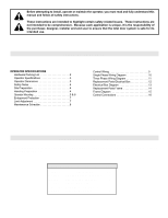
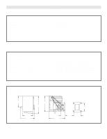
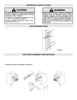
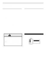
IMPORTANT SAFETY NOTES CAUTION WARNINWG ARNING TO AVOID DAMAGE TO DOOR AND OPERATOR, MAKE ALL DOOR LOCKS INOPERATIVE. SECURE LOCK(S) IN "OPEN" POSITION. IF THE DOOR LOCK NEEDS TO REMAIN FUNCTIONAL, INSTALL AN INTERLOCK SWITCH. DO NOT CONNECT ELECTRIC POWER UNTIL INSTRUCTED TO DO SO. KEEP DOOR BALANCED. STICKING OR BINDING DOORS MUST BE REPAIRED. DOORS, DOOR SPRINGS, CABLES, PULLEYS, BRACKETS AND THEIR HARDWARE MAY BE UNDER EXTREME TEN- SION AND CAN CAUSE SERIOUS PERSONAL INJURY. CALL A PROFESSIONAL DOOR SERVICE- MAN TO MOVE OR ADJUST DOOR SPRINGS OR HARDWARE. CAUTION SITE PREPARATIONS It is imperative that the wall or mounting surface provide adequate support for the operator. This surface must: a) Be rigid to prevent play between operator and door shaft. b) Provide a level base. c) Permit the operator to be fastened securely and with the drive shaft parallel to the door shaft. Shaft Support Bracket with Bearing (Not Supplied) Door Sprocket The safety and wear of the operator will be adversely affected if any of the above requirements are not met. For metal buildings, fasten 2" x 2" x 3/16" (or larger) angle iron frames to the building purlins. For proper spacing, retain .2.75" between. See Figure 1. 22.-715/4" FIGURE 1 OPPOSITE HANDING PREPARATIONS Shipped from the factory for either left hand or right hand mounting. Refer to next to last digit in the model number for handing of your unit. If necessary, model MGJ may also be field modified to accommodate opposite handing. Refer to the conversion instructions below and on page 5. 1. Remove Disconnect Assembly Components Remove the master link from the limit chain, remove the chain and set it aside. KEYS SPRING DISCONNECT HUB Remove the two E Rings securing the sprocket on the gear reducer shaft. Remove the screws securing the yoke to the disconnect shaft, set the yoke aside. E RING SPROCKET BRACKET YOKE SHAFT DISCONNECT LEVER 4
-
 1
1 -
 2
2 -
 3
3 -
 4
4 -
 5
5 -
 6
6 -
 7
7 -
 8
8 -
 9
9 -
 10
10 -
11
-
12
-
13
-
14
-
15
-
16
 |
 |